The function of the condenser is to act as a heat exchanger to dispel the heat energy contained in the refrigerant. Superheated vapour enters the condenser at the top and subcooled liquid leaves the condenser at the bottom. The condenser must be highly efficient but as compact as possible.
The pressure and temperature has been raised by the compressor. There is a need to lower the temperature of the heat laden refrigerant to change it back into a liquid enabling it to act as a cooler again later in the system. To do this the refrigerant flows into the condenser as a vapour and gives off heat to the surrounding area and most of the refrigerant (depending on system load) condenses back into a liquid which then flows into the receiver/drier.
The condenser is located at the front of the vehicle where strong air flow through its core can be achieved when the vehicle is in motion. To aid the removal of heat when the vehicle is stationary or at a low speed the condenser is fitted with a single or double fan system. Shrouds are often used to direct the air flow over the surface of the condenser.
Condenser design
The ideal condenser should have no pressure drop between the inlet and the outlet. Condensers are generally made from aluminium to prevent any chemical reaction between the metal and refrigerant/oil mixture. They are generally constructed with tubes and fins. Tubes to carry the

Serpentine fin type

Tube and plate type
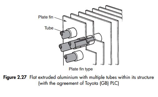
Tube and plate and fin types have been used for a number of years and can be seen on R12 systems but are not generally used on R134a systems. This type of condenser can also be backflushed to remove any foreign particles within the system.
Parallel flow type (a flat tube condenser)

Parallel flow condensers are very efficient, the condenser breaks up the flow into tiny streams enabling it to transfer heat more rapidly. This type of condenser cannot be flushed and if it becomes blocked can only be replaced.
Condenser refrigerant flow

The flow of refrigerant is either serpentine (Fig. 2.29) or parallel flow (Fig. 2.30). Serpentine flows through the tube(s) evenly eventually condensing while following the same path.
Parallel flow allows the path of the refrigerant to go vertically as well as horizontally across the condenser. Parallel flow is considered to be the more efficient layout.The key to the design is the header tanks/manifolds fitted to the sides of the core allowing the flow to break up into small streams.
Dual condenser
This layout includes a condenser with an integrated multi-flow condenser (Fig. 2.31) and a gas/liquid separator (modulator) – a subcool cycle. In simple terms these are two condensers stacked on top of each other with a receiver drier called a modulator between the two. They are generally used in vehicles with large internal space and cooling requirements. Refrigerant flows through the first parallel flow condenser and then into the modulator as a liquid. Any gaseous refrigerant which the first condenser was unable to condense will travel with the liquid refrigerant to the subcooling portion of the condenser to ensure only liquid refrigerant flows to the FOV (Fixed Orifice Valve) or receiver-drier.

The condenser is the point within the A/C system which is used to remove the unwanted heat. This makes it very important in the overall efficiency of the system. As the latent heat of condensation is transferred to the air stream, the refrigerant vapour makes the necessary change into liquid.


useful information on topics that plenty are interested on for this wonderful post.Admiring the time and effort you put into your b!..
ReplyDeleteAirconditioning