This section describes a range of sensors and actuators used in common A/C systems. It describes the underpinning theory associated with the sensors and actuators and provides practical examples of their application, and also includes wiring diagrams and measured data in various forms representing the output of a sensor or control signal used for an actuator. The sensors and actuators included are as follows:
Sensors:
- Temperature – NTC and PTC.
- Sun load – photovoltaic and solar cells.
- Pressure – capacitive, strain gauge, piezoelectric.
- Position – linear and rotary potentiometer.
- Speed – Hall effect and inductive.
- Humidity – capacitive.
- Pollution – metal oxide semiconductor (MOS).
Actuators:
- Solenoids – relays, coolant valves.
- Motors – permanent magnet.
- Stepper motors – DC permanent magnet, variable reluctance, hybrid.
Temperature sensor
Theory of operation
A temperature sensor uses direct measurement. It is a temperature dependent, non-linear semi- conductor which is termed ‘thermistor’. It comes in various packages and is fitted in a range of environments.Temperature sensors are generally NTC or PTC type semiconductor material.
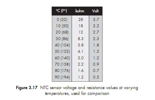
NTC temperature sensor
These are generally made from different oxides of metals such as iron, cobalt, nickel copper and zinc. The sensor is extensively used in temperature measurement. The NTC (Negative Temperature Coefficient) thermistor, decreases in resistance as it increases in temperature. The sensors are generally arranged in a potential divider circuit with a fixed resistor.The fixed resistor will be inside the control module to allow the module to measure a variation in voltage or current, see Figure 3.2.

hal 130-
Sensor monitoring locations:
Engine coolant temperature sensor – direct measurement of coolant temperature. Ambient temperature sensor – fitted near the condenser/front bumper. Evaporator temperature sensor – fitted to the evaporator to measure its surface temperature informing a module to control the compressor in case icing occurs. Cabin temperature sensor – integral to the A/C controls panel and/or fitted to the air ducting.
Sensor failure
If a temperature sensor like the exterior temperature sensor fails, then often the A/C module will apply a fixed temperature value, e.g. 10°C. If the interior temperature sensor fails then a temperature of approximately 24°C is fixed.This allows the system to operate with a fault.
An example application is an air vent outlet and interior temperature sensor with integrated fan (Figure 3.18)
Sensor monitoring location:
Built into the heater controls or
Fitted to the air ducts.
The sensor unit has a small electric fan (Fig. 3.18) to prevent distortion of the temperature due to heat build-up.The outlet and cabin temperature sensors are the most important values for the A/C control unit.A comparison is made between the cabin temperature and the desired temperature in order to decide if the mixed-air temperature should be increased or decreased. The cabin temperature is adjusted with respect to the outside temperature so that the temperature experienced matches the set temperature.As the difference between selected tempera-ture and adjusted temperature icreases, the interior fan speed will increase.When the ignitionis turned off, the suction fan on some systems may continue to operate for up to 10 minutes. This decreases the risk of incorrect temperature value when restarting after a short stop.

Sensor wiring diagram
The motor is powered by the A/C control module (Fig. 3.19). Some systems will have the unit built inside the module while other systems have a separate unit near the centre vent area to accurately measure interior temperature. The motor will be powered by a 12V feed and the sensor by a 5V feed.The sensor will be a part of a potential divider circuit enabling the measurement of a volt drop across a fixed resistor situated inside the module. The technician is able to measure the volt drop across the sensor by placing a voltmeter or oscilloscope (trend measurement) across pins 4 and 6.
Waveform
The plot in Fig. 3.20 shows the volt drop across an NTC sensor.As the temperature applied to the sensor by the A/C system increases the resistance reduces with a corresponding reduction in volt drop.A DC analogue signal can also be measured using the Min and Max selection of an oscilloscope. This enables the measurement of the total variation in voltage to be known which can be compared to a known value for analysis.
Signal checks:
- Measuring the temperature of the air flowing past the sensor to carry out a comparisonshould be carried out.

- The waveform should correspond to an NTC or PTC graph (Figs 3.16 and 3.22).
- The peak voltage should be referenced to the specification of the sensor.
- Voltage transitions should be steady and reflect a change in temperature.
The measured temperature of the face vent outlet temperature at the start of the waveform is 2.58V at 4°C and 0.55V at 60°C.
Data logger

PTC temperature sensor/element
These are generally made from barium titanate. A characteristic of a positive temperature coefficient sensor/element is that there is an increase in resistance due to an increase in temperature. The increase in temperature can also be caused by the current flowing through the sensor.A PTC element can be used as a protection device, overload protection due to a large heating effect from the current flow.When the current flows and the element increases in temperature its resistance also increases, this has a counter effect and reduces the current flow. This characteristic prevents the PTC element from overheating.

PTC material can also be used in electric heating systems, see Chapter 1, section 1.2.
Example recirculation flap controlled by PTC sensors The air recirculation flap on some A/C systems is operated by a DC motor.The flap has only two positions (100% open or 0% closed).When the motor has turned the flap to one of the end positions, the current passing through the motor winding is limited by two PTC resistors built into the motor. Once the motor reaches its maximum position the current will increase and heat the PTC sensors.The sensors increase in temperature and reduce the current flow due to a corresponding increase in resistance.
Sensor monitoring location:
1. Fitted inside the recirculation motor which is attached to the recirculation flap.
Sensor failure
If a temperature sensor like the exterior temperature sensor fails, then often the A/C module works with a fixed temperature value, e.g. 10°C. If the interior temperature sensor fails then a temperature of approximately 24°C is fixed.This allows the system to operate.
Sun load (photovoltaic diode and solar cells)
Theory of operation
The sun load sensor (Fig. 3.26) can be a photoelectric diode which is designed to exploit the photovoltaic effect and measures sun intensity. If a voltage in reverse bias is placed across the diode and light is directed on it, a reverse current will flow (photovoltaic current).Exposing the diode to

light energy produces more electron hole pairs (free charge carriers) which pass the junction of the diode and increase current flow.The amperage of this current is proportional to light intensity.
Sensor monitoring location:
1. The sensor is located above the instrument panel near the windshield.
Explanation of P and N type material (Fig. 3.25)
N type
Once impurities are added to a base material their conductive properties are radically affected. For example, if we have a crystal formed primarily of silicon (which has four valence electrons), but with arsenic impurities (having five valence electrons) added,we end up with ‘free electrons’ which do not fit into the crystalline structure.These electrons are loosely bound.When a voltage is applied, they can be easily set in motion to allow electrical current to pass. The loosely bound electrons are considered the charge carriers in this ‘negatively doped’ material,which is referred to as N type material.The electron flow in an N type material is from negative to positive.This is due to the electrons being repelled by the negative pole and attracted by the positive pole of the power supply.
P type
It is also possible to form a more conductive crystal by adding impurities which have one less valence electron. For example, if indium impurities (which have three valence electrons) are used in combination with silicon, this creates a crystalline structure which has ‘holes’ in it, that


is, places within the crystal where an electron would normally be found if the material was pure.These so-called ‘holes’ make it easier to allow electrons to flow through the material with the application of a voltage. In this case, ‘holes’ are considered to be the charge carriers in this ‘positively doped’ conductor, which is referred to as P material. Positive charge carriers are repelled by the positive pole of the DC supply and attracted to the negative pole; thus ‘hole’ current flows in a direction opposite to that of electron flow.
Sensor failure
If the sun load sensor fails, the A/C module works with a value corresponding to darkness. Photo diode can be tested using a powerful 60W light.This will alter the light intensity and vary the sensor’s output. If more than one sensor is housed within the sun load sensor, for example dual zone A/C with left and right photo diodes, the light is placed towards one side to test the sensor and more towards the opposite side to test the other sensor.This can be monitored via a scope, diagnostic tester or volt/current meter.An amp clamp (low current sensing clamp) could be fitted to measure the current flow, access permitting.
Wiring diagram
The sensor (Fig. 3.28) receives a 5V signal from the A/C module pins 1 and 2.The A/C module will also have resistors in series with both the left and right sensor. This will provide a potential divider circuit.The division will be based on the amount of light falling on the diode causing it to conduct in a reverse bias direction. Pin 3 is the sensor ground (earth).
A typical sensor that works on the photo diode principle has the following output:
Dark signal voltage: 4.6 volts measured at pin 22/23
Light signal voltage: 0.4 volts measured at pin 22/23
Data logger

Sun load sensor using solar cells
A solar cells converts light energy into electrical energy. The sensing element contains a PN junction, so the charge is carried separately in its electric field before proceeding to the metal contacts on the semiconductor’s surface (see page 118 for an explanation of P and N type material.A DC electric (photoelectric voltage) is produced across the terminals; the electrical potential is between 0.5 and 1.2V depending on the semiconductor material being used. Silicon is the most common material for solar cells.

Sun load sensor (infrared)
Theory of operation
Infrared radiation lies in the optical waveband and forms part of the electromagnetic spectrum. The infrared range is adjoined by visible light of long wavelengths. Every warm body releases infrared radiation.The higher the body’s temperature the more energy is released in the form of infrared radiation.This makes the measurement of heat source and intensity possible with infrared sensors.The infrared sun load sensor is situated on the top of the dashboard and contains five infrared-sensitive elements: left, right, front, rear and top. It is supplied with power in the form of battery pulses from the climate control module. Voltage from the five sensor elements is sent consecutively to the climate control module. For the control module to be able to detect which sensor element is reporting, the transmission is preceded by the pulse pattern 5V–0 V–5V. The control module synchronises the solar sensor pulse transmission by sending short ground pulses at 25Hz from pin 16. With the voltage from the five sensor elements, the control module calculates the solar intensity, azimuth and height.The values are used to calculate the current temperature at head height for the front seat passenger
and driver.
Pressure sensor – capacitive type
Theory of operation
The pressure sensor contains two metal plated ceramic discs mounted in close proximity. The disc located closest to the pressure connection is thinner and bends when subjected to pressure. By this means, capacitance between the metal plating of the discs is changed based on the pressure. A circuit integrated in the sensor converts the capacitance to an analogue voltage. Capacitive measurements are based on the principle of a capacitor with the physical property of storing electrical charge. Its ability to store a charge is based on the distance between the two plates, size of the plates and the material it is made from.The distance is the main variable which determines the plates’ charge difference. If the plates are far apart then this creates a low charge difference (Figure 3.31). If the plates are close together then the charge difference will increase proportionally (Figure 3.32). Linear pressure sensors allow for greater fan control.
Sensor monitoring locations:
1. A/C high pressure sensor is fitted to the A/C pipe work or receiver-drier.
Waveform
The trend plot (Fig. 3.33) shows the A/C system off, producing a voltage reading of 1.3 volts and a
pressure of approximately 5 bar. The A/C was then switched on under light load; the voltage
increased proportionally with an increase in pressure. The A/C stabilised at a voltage of approxi-
mately 2 volts which is approximately 12 bar.The load on the system was increased by setting the
interior temperature to the lowest value on the climate control system (low 16°C) and increasing
the blower speed to maximum.This caused the sensor voltage to peak at 2.2 volts, approximately
13.5 bar.


Signal checks:
- Monitor a steady change in voltage level directly proportional to a change in pressure.
- Check for glitches in the signal (drops to zero or rise to reference voltage).
- Volt drop on the reference voltage and ground signal should not be greater than 400mV (see Power-to-power test and Earth-to-earth test under section 3.3).

Pressure sensor using strain gauge
Theory of operation
A micro-machined membrane sensor with a strain gauge is used to measure pressure. A strain gauge is a group of resistors printed onto a membrane in the form of a bridge circuit (Wheatstone bridge).The bridge circuit Figure 3.37 shows four resistors (two series resistors in parallel with each other). The potentials at points UM are equal when the bridge is balanced (both sets of parallel resistors have the same potential difference across them).When pressure is applied to the sensor’s membrane the resulting mechanical force changes the electrical resistance of some of the resistors.The resistors are arranged so that two resistors increase in length and two resistors decrease in length due to deformation.This causes the bridge to become unbalanced giving a potential difference output across point UM. The output of the potential difference is proportional to the deformation of the membrane. It is important to remember that resistance is proportional to length and inversely proportional to cross-sectional area. By changing the shape of the resistors the bridge becomes unbalanced.The sensor and the hybrid circuitry for signal processing are located together in a single housing.
Sensor monitoring locations:
1. A/C high pressure sensor is fitted to the A/C pipe work or receiver-drier.

Pressure sensor using piezoelectricity
Theory of operation
The piezoelectric effect can best be illustrated by means of a quartz crystal on which pressure is exerted. The quartz crystal is electrically neutral in its rest state, that is, the positively and negatively charged atoms (ions) are in balance. External pressure exerted on a quartz crystal causes the crystal’s lattice to deform. This results in ion displacement. An electric voltage is generated as a consequence. The direct piezo effect is primarily utilised in sensors. Today’s technologies use high performance piezoceramic materials instead of quartz crystals.As sensors, piezoceramics convert a force acting upon them into an electrical signal when the ceramic material is compressed against its high rigidity.Owing to dielectric displacement (dielectric electrically non-conductive), surface charges are generated and an electric field builds up.This field can be registered as a (measurable) electrical voltage via electrodes. In the case of sensors, mechanical energy is converted into electrical energy by means of a force acting on a piezoelectric body.
Sensor monitoring locations:
1. A/C high pressure sensor is fitted to the A/C pipe work or receiver-drier.
figure 3.38
Angle sensors (potentiometer)
Theory of operation
An angle sensor simply measures the angular rotation of a component (e.g. air distributor door
or throttle valve). Figure 3.39 shows a sliding contact and a control track.A reference voltage
for the sliding contact is supplied via a contact track. This contact track has a constant, low
ohmic resistance from start to end.The sliding-contact position sensor is actuated by the move-
ment of the distribution door (which is actuated by a motor), the resistance of the variable resist-
ance track changes along its length.The sensor track operates on the principle that resistance
is proportional to length and inversely proportional to cross-sectional area.This means if you
double the length of a conductor the resistance will double and if you halve the cross-sectional
area of a conductor the resistance will double.The slider moves across the track measuring the
voltage at different points.
figure 3.39
3.40
3.41
The rotary distribution door has a DC permanent magnet motor (not shown) with a poten-
tiometer which provides closed loop feedback to verify its position.
A reference voltage and ground is applied to the resistive track.This creates a 5V volt drop
across the resistor. The signal output sliding contact makes contact with the surface of the
resistive track and divides (potential divider circuit) the circuit creating two volt drops across
its length (Fig. 3.41).
If the sliding contact position sensor is in the middle of the resistive track, 50% of travel has
occurred on the rotary door.Then the volt drop theoretically should be equal at 2.5 volts.This
is due to the resistor track being divided into two halves of equal proportion so equal volt
drops exist.
If the rotary distribution door is closed, which represents a 0% movement ratio, then the
output of the sensor would be very low at around 0.1V due to a low resistance between the ref-
erence voltage and the output. If the rotary door was in the fully open position, 100% move-
ment ratio, then the volt drop would be high due to the high resistance.
A formula to calculate voltage output (Vout) of a rotary sensor:
rumus
figure 3.42
3.43
rumus
Pressure sensor sliding contact potentiometer (linear)
A linear potentiometer (Fig. 3.43) operates on the same principle as a rotary potentiometer
except the movement is linear and not rotary, hence its name. Pressure from the refrigerant is
applied to a membrane that deforms and transfers this movement to the potentiometer slider (1).
This varies the linear movement and the sensor’s output.
Sensor monitoring locations:
1. A/C pressure sensor (linear measurement) is fitted to the A/C pipe work Schrader valve or
receiver drier housing (high pressure side of A/C system).
2. Throttle position (angle measurement) is found in the throttle housing, accelerator pedal
position.
3. Heater door position feedback is attached to heater door motor or mechanism.
figure 3.44
Waveform
The waveform represents an increase in voltage output with a corresponding increase in angu-
lar movement.
rumus
Signal checks:
1. Monitor a steady change in voltage level directly proportional to a change in rotary or lin-
ear motion.
2. Check for glitches in the signal (drops to zero or rise to reference voltage).
3. Volt drop on the reference voltage and ground signal should not be greater than 400mV
(see Power-to-power test and Earth-to-earth test under section 3.3).
4. Min and max values indicate maximum angular or linear motion.
5. Signal noise may indicate worn or faulty wiper contact.
Speed sensor (Hall effect)
Theory of operation
If a current flows through an electrical conductor positioned at right angles (90°) to a magnetic
field, the charge carriers (electrons) are deflected (Lorentz force).The Hall effect (Figs 3.45 and
3.46) is generated by means of a semiconductor plate (Hall plate) which receives a defined volt-
age (U).Application of the supply voltage U results in an evenly distributed electron flow over
the entire surface of the Hall plate.As a result, a magnetic field builds up around the Hall plate.
The evenly distributed electron flow leads to charge equalisation (UH 0V) on both sides of the
Hall plate.
Note – changes in the magnetic field lead to corresponding changes in electron flow. If the
north pole of a permanent magnet meets the north pole of a Hall plate magnetic field, the
field moves away from the permanent magnet.
As a result, the electrons (negatively charged particles) driven by the longitudinal potential
are suddenly deflected vertically with respect to the current’s direction of flow, away from the
permanent magnet (repulsion of electron flow).The resulting charge difference between the two
sides of the Hall plate gives rise to a Hall voltage(UH ). If the south pole of a permanent magnet
figure
3.45
3.46
meets the north pole of a Hall plate magnetic field, the field moves toward the permanent mag-
net.As a result, the electrons (negatively charged particles) driven by the longitudinal potential
are suddenly deflected vertically with respect to the current’s direction of flow, toward the per-
manent magnet (attraction of electron flow). The sudden changes in electron flow correspond-
ingly change the polarity of the Hall voltage (from positive to negative or vice versa). Hall
voltages are generally very low. Lying in the millivolt range, these voltages must be processed
appropriately. Sensor technology usually makes use of Integrated Circuits (ICs) to process Hall
voltages and output them as square-wave signals to the terminal device (e.g. PCM).The square-
wave signals can be made visible with the aid of an oscilloscope or tested with an LED.
Note – The Hall plate magnetic field can also be deflected by moving an iron element (e.g.
a ferrous pulse wheel) toward it. In this case, there is no alternation of electron flow
between the sides of the Hall plate.The magnetic field and electron flow are always dis-
placed in just one direction: from charge equalisation to charge difference (0 signal edge/
high signal edge).
Sensor Monitoring locations:
1. Interior blower speed feedback is fitted on blower inside heater assembly.
2. Vehicle speed sensor is fitted on the transmission housing output shaft.
Example vehicle speed sensor
Vehicle speed is an important factor used to assist in calculating the cooling rate of the interior
due to increased natural flow rates (ram air).Often an increase in vehicle speed will cause the
control module in automatic mode to reduce the blower speed (automatic climate control sys-
tem).The accuracy of the exterior temperature sensor is also adversely affected by the ram air.
For this reason, the A/C module calculates the exterior temperature from the measurement of
the exterior temperature sensor and vehicle speed.The vehicle speed is detected by the Vehicle
Speed Sensor (VSS),which also supports other systems (speedometer, PCM (Powertrain Control
Module), suspension, braking). It is designed as a Hall sensor and sends a digital signal to the
A/C module in the form of a square-wave signal.
figure 3.47
3.48
Signal checks:
1. Monitor a steady change in frequency which is proportional to a change in vehicle speed.
2. Check for glitches in the signal (drops to zero or rises to reference voltage).
3. Volt drop on the reference voltage and ground signal should not be greater than 400mV.
4. Peak–peak voltages should be the same and equal reference voltage, allow 400mV differ-
ence (see Power-to-power test and Earth-to-earth test under section 3.3).
5. The lower horizontal lines should almost reach zero, allow for 400mV difference.
6. Signal transitions should be straight and vertical.
7. Check for any background interference.
Inductive type speed sensor
Theory of operation
Figure 3.49 shows a permanent magnet with north and south poles.An electrical conductor is
positioned between the north and south poles. If the conductor is moved in the direction of the
arrow, it intersects with the permanent magnet’s field lines. Charges inside the conductor are
displaced in this process. Free electrons move to one end of the conductor. Correspondingly, a
shortage of electrons occurs at the other end. If you can arrange for the conductor to keep
moving in the magnetic field then you will have a continuous force of electrons available to do
work.The resulting potential between the conductor’s ends is termed induction voltage.
Sensor monitoring locations:
1. Compressor speed sensor – measures the rotational speed of the pulley or main compres-
sor shaft.
2. Blower motor speed sensor – measures the rotational speed of the blower motor for feedback
control.
figure 3.49
3.50
The inductive speed sensor contains a permanent magnet and soft permeable pole pin sur-
rounded by a coil.The speed sensor is mounted so that its front face is a defined distance from
the sensor ring.The rotation of the sensor ring induces a voltage proportional to the periodic
variation in magnetic flux.The variation in magnetic flux is caused by the movement of the ferro-
magnetic sensor ring.When the magnetic flux increases or decreases an emf is induced into the
coil windings.As a tooth of the ring approaches the sensor a positive emf is generated in the
coil due to the lines of flux being cut in the magnetic field.When the tooth is aligned with
the sensor there is no change in magnetic flux so the emf is zero. As the tooth rotates away
from the sensor it again breaks the lines of magnetic flux which generates a negative emf. The
changes in the magnetic flux induce an alternating voltage in the inductive sensor coil.A uniform
tooth pattern will create a near sinusoidal voltage curve.
Waveform
Voltages generated by induction constantly alternate in amplitude and polarity (Fig. 3.51).
Accordingly, they are also termed alternating voltage.Alternating voltage rises from 0V to its
positive peak value (amplitude), then drops back via the 0V level to its negative peak value,
figure 3.51
rises again to its positive peak value etc. The number of complete alternations (periods) per
second is termed the voltage frequency.
The air gap of this particular type of sensor is crucial to its operation.Because air is not very
permeable if the gap is too large the amplitude of the output is very low or zero.
Humidity sensor
Theory of operation
Humidity sensors determine relative air humidity using capacitive measurement technology.
For this principle, the sensor element is built out of a film capacitor on different substrates
(glass, ceramic etc.). The dielectric is a polymer which absorbs or releases water proportional
to the relative environmental humidity, and thus changes the capacitance of the capacitor,
which is measured by an onboard electronic circuit (see Pressure sensor – capacitive type
(above) for additional information).
A temperature sensor is often used with a humidity sensor.The temperature and humidity
sensors together form a single unit, which enables a precise determination of the dewpoint
without incurring errors due to temperature gradients between the two sensor elements. The
sensors are coupled to an amplification, analogue-to-digital (ND) conversion and serial inter-
face circuit all on the same chip.The integration provides improved signal quality and insensi-
tivity to external disturbances (EMC).
Air quality sensor
Theory of operation
If the vehicle is in an exhaust gas cloud, the air intake process will always be stopped and the
system will switch to recirculation mode.This is to prevent the air quality in the passenger com-
partment from becoming contaminated by the air outside.Recirculation will also be disengaged
if the mode was permanently on and the air in the passenger compartment was not being
exchanged at all; in this case the system works dynamically. In exceptional cases such as these,
the mode of operation ensures that an adequate supply of fresh air is fed into the system.
An Air Quality Sensor (AQS) (Fig. 3.52) is located in the main air inlet duct of the HVAC
system.When the threshold for carbon monoxide or nitrogen dioxide is reached, the AQS rap-
idly communicates to the HVAC system to initiate the air recirculation mode.The Metal Oxide
Semiconductor (MOS) sensor consists of a sensing material and a transducer (substrate).
Surface reactions at the sensitive layer change its resistivity.The transducer keeps the sensing
material at an elevated temperature, and its resistance is measured. Changes in the composi-
tion of the ambient atmosphere create a corresponding change in the resistance of the sensing
layer, allowing the sensor to detect a wide range of toxic gases even at very low concentrations.
The sensing layer is a porous thick film of polycrystalline tin oxide (SnO2). In normal ambient
air, oxygen and water vapour-related gases are absorbed at the surface of the SnO2 grains. For
reducing gases such as CO, a reaction takes place with the preabsorbed oxygen and water
vapour-related gases which decreases sensor resistance.
1. Sensor monitoring location:Main air inlet duct of the HVAC system.
The sensor uses integrated signal conditioning electronics mounted with the sensing element
on a circuit board.An integral microcontroller monitors the pollution level and creates a Pulse
Width Modulated (PWM) or serial output signal in relation to pollution levels.
Benefits:
● Improved comfort.
● Fast, automatic protection against potentially harmful external pollutants.
● Cabin pollutant concentrations reduced by 20%.
● Occupant discomfort due to odours reduced by 40%.
figure
3.52
3.53
3.54
Actuators
1. Relay.
2. Solenoids.
3. DC permanent magnet motor.
4. Stepper motors – variable reluctance, permanent magnet and hybrid.
Relay
Theory of operation
Current flowing through a conductor like a straight copper wire creates a magnetic field
around itself. If the copper wire is twisted (Fig. 3.55) and shaped like a coil and current passed
through it then a magnetic flux is created. The relationship between the direction of current
flowing through a conductor and the direction of magnetic flux is expressed by ‘Ampere’s rule
of the right-hand screw effect’. If the current is reversed then the magnetic poles will reverse.
If a permeable material (material easily magnetised) is placed under the coil it will become
magnetised and attracted by the magnet field generated in the coil.The action of the coil and
current is the principle of electromagnetic force.The force created is not strong enough in Fig. 3.55
figure 3.55
3.56
3.57
to move the metal piece. If an iron core is inserted (Fig. 3.56), the number of magnetic fluxes is
intensified and the metal is under a greater force. This is because the coil and the bar create
lines of magnetic force.This principle explains the operational characteristics of a relay.
Actuator example relay
In Figure 3.57 a current flows through the relay coil (6) and creates a magnetic field, which is
magnified by the coil’s core (7).This Magnetic Motive Force (MMF) is applied to the armature
(2) and it is attracted to the centre of the coil. The force is great enough for the armature to
overcome spring force and the armature makes contact with the coil.Contact points are attached
to the armature. Once the armature has made contact with the coil the relay contacts are
closed from (4) to (5).This creates a closed circuit on the high current side of the relay.
Relays are electrically controlled switches.The function of a relay is to use a low current to
operate a high current. The switch inside the relay will be in one of two positions, depending
on whether the electromagnetic relay coil is energised or de-energised. In basic relays, there is
one input and either one or two outputs. Relays are either Normally Open (NO) or Normally
Closed (NC). In either case, the relay switch input (Fig. 3.59a) is always connected to pin 30.
Pin 30 not only designates the input to the relay switch, but in accordance with DIN standards,
we also know that it’s connected to battery positive.The relay outputs on the other side of the
relay switch are designated either 87, 87a or 87b.The two remaining relay terminals are connected
to the relay coil.Applying current to the coil is what makes the relay close or open.According
to DIN standards, pin 85 should be connected to ground (usually controlled by another switch)
and pin 86 should be connected to battery positive (usually protected by a fuse). This uses a
low current (switched by the A/C module) to operate the relay thus switching on a consumer
which uses a large current (condenser fan). This means that the relay must have at least two
circuits, a low current and a high current circuit.
The relay in Fig. 3.58 shows two circuits running vertically.The left which obtains its power
from fuse F30 (15A) is the low current side (switching side). The right circuit is the high cur-
rent side (switched side).Generally the switching side is operated by a switch or a module and
the switched side operates a high current consumer like the compressor or condenser fan.The
diode is used to protect the switching device (generally a control module) from back-emf.
figure 3.58
3.59
Relay pin coding
DIN standard 72 552 pin codes and ISO pin designation
Testing relays
Table 3.1 offers some appropriate tests for a relay.
Some common relay applications:
● A/C relay.
● WOT (Wide Open Throttle) relay for the compressor clutch.
● Blower motor relay.
● Condensor fan relay.
Actuator locations:
1. Battery junction box, central junction box.
Solenoid
Theory of operation
A solenoid (Fig. 3.60) operates in a similar manner to a relay except when a permeable mate-
rial like an iron bar is inserted into a coil shaped like a cylinder and current flows through the
coil, the bar is pulled to the centre of the coil. The applied current can be DC,AC, or a pulse
width modulated control signal.
A water control solenoid can be used as an example (Figure 3.61). The key to lifting the
plunger inside the valve body is the generation of magnetism ‘lines of force’. These lines of
force need to be strong enough to move the mass of the plunger (the so-called iron bar).They
quite often need to be strong enough to overcome a spring force (used to hold the plunger
closed) and the force of gravity (plunger is in the vertical position).The more lines of force the
stronger the magnetic field or ‘flux ( )’.The unit for flux is the weber (Wb).The flux density
(B) of a magnetic field is the amount of flux (Wb) per unit area perpendicular to the magnetic
field. The unit for magnetic flux density is either the weber-per-metre-squared or tesla which
has the designated letter (B). Another factor, which determines the strength of a magnetic
field, is reluctance. Reluctance is the ratio of magnetic motive force (mmf) to flux in a mag-
netic conductor. It is the equivalent to electrical resistance and so is proportional to length and
inversely proportional to cross-sectional area.The unit of reluctance is the ampere-per-weber
and is designated the letter (R).
figure 3.60
Multimeter
Volt drop tests This test involves placing the voltmeter leads across the input and
output to the relay contacts (pins 87 and 30) (pins 5 and 3). The maximum volt
drop should not exceed 0.5 V.
A current test is the preferred test. A fuse which is in series with the circuit can
be removed and the meter placed in series by placing the meter across the fuse
terminals. Current measurement is taken to test the relay under load. Relays are
current rated so information is available.
A resistance measurement can be made of the coil and the relay contacts. The
relay coil will have a low resistance of approximately 2–3 ohms.
Continuity To test the sensor contacts (right circuit) the relay would have to be
removed from its fuse box and current passed through the switching side. This
means that current would pass through the left side circuit to be able to measure
using a multimeter the resistance of the right side. The resistance value may not
be known so all you would be testing is continuity.
A diode test can be used to ensure the diode operates correctly inside the relay.
The diode should have continuity in one direction and have an infinite resist-
ance in the opposite direction.
Power probe (with built-in LED display)
The use of a power probe is ideal to power a relay. Technicians often remove
the relay and apply power to the relay female connectors inside the fuse box
housing. This is done when they are confident that the relay is faulty and a test
is required to check the response of the system. The power probe can also be
used to power the relay itself to check audibly or via a meter that the relay
contacts are closing.
The LED display is ideal when checking earth switched pins of the relay. This is
done by removing the relay and placing the power probe on the earth switch
terminal (controlled by the A/C module). When the A/C module tries to switch
the earth path of the relay on your power probe green (green for ground) the
LED will illuminate.
Serial test
Relays that send power to a module and are sometimes represented on data
lists. Fault codes can be accessed for power supply faults. Actuator command
can be used to operate some relays, depending on the ability of the serial
tester.
Break-out box testing
Very useful for pinpointing power supply problems. Checked by using either an
oscilloscope or multimeter connected to pins on the break-out box which are
powered by relays.
Oscilloscope
Very useful for measuring any background interference or electrical noise within
the circuit and checking any volt drop going to and across the relay (under
load).
Power to power test This is when the leads of the meter are placed one on the
battery terminal and one to the supply of the relay. This is to check that the relay
supply voltage is good. The maximum volt drop should not exceed 0.5 V.
Earth to earth test This is when the leads are placed on the earth of the relay
and the earth of the battery. This checks that the earth path is good. The maxi-
mum volt drop should not exceed 0.5 V.
The coil creates an mmf, which drives flux left through the plunger, then around the frame
of the solenoid then through the air gap and back into the plunger.The reluctance of this path
s mostly made up by the air gap.When the plunger is out (valve is closed), the reluctance is
quite high.When current is applied to the coil, the plunger moves to the top and the reluctance
decreases (due to a smaller air gap).This is an example of forces in magnetic systems; they act
to reduce the reluctance, or increase the inductance. Eventually, the plunger will collide with
the frame at the top, the air gap will be zero, and the reluctance will be at a minimum.
The main variables for the performance of the solenoid are the following:
1. Plunger shape.
2. Plunger material.
3. Number of windings around the plunger.
4. Supply voltage/current flow through windings.
5. Wiring configuration of the coil.
6. Air gap.
Example water control valve
In water-based heating systems, the heater control valve interrupts the coolant circuit between
the engine and the heater core. The valve contains a plunger which closes off the openings
between the feed from the engine and the return to the heater core.The solenoid valve is fully
open when de-energised.
figure 3.61
3.62
During testing, the temperature control should be brought to the centre setting. The valve
must open and close regularly, approximately 18 times per minute when the engine is running.
Electric motor permanent magnet
Theory of operation
All conventional electric motors depend for their operation on a conductor such as a wire or
a coil creating or operating within a magnetic field. Current flowing through a conductor like
a straight copper wire creates a magnetic field around itself. The relationship between the
direction of current flowing through a conductor and the direction of magnetic flux is expressed
by ‘Ampere’s rule of the right hand screw effect’. If this conductor is placed between the poles
of a magnet and current is passed through it.There will be a reaction between the two magnetic
fluxes produced.
The strength of the electromotive force varies in proportion to the density of the magnetic
flux, the current flowing through the conductor and the length of the conductor within the
magnetic field.
The magnitude of the force varies directly with the strength of the magnetic field and the
amount of current flowing in the conductor:
rumus
If a conductor formed in the shape of a square coil (Figs 3.63 and 3.64) is placed between the
north and south poles of a magnet and a commutator segment is fitted to the end of the coil
with brushes to enable an electrical contact, an interesting relationship occurs.
figure 3.63
3.64
When no current flows through the conductor only one magnetic flux is present, which is
created by the permanent magnet (Fig. 3.64).When current flows from the battery to the con-
ductor via the brushes and commutator a magnetic flux is produced.The composition of the mag-
netic fluxes from the magnets and the conductor creates reactive forces (F1 and F2).The reactive
forces are in different directions due to current flowing forwards on the left side of the square
coil and in the opposite direction on the right side of the square coil; this is due to the layout
of the conductor within the magnetic field.The direction of the two forces F1 and F2 adheres
to ‘Fleming’s left hand rule’ and causes the conductor to rotate around its axis P. Problems
occur when the conductor rotates vertically and counter forces are created that try to reverse
the direction of the conductor.As a solution (Fig. 3.65) to this problem individual commuta-
tors are fitted to each end of the coil to periodically reverse the current flow whenever rotated
180°; this allows the magnetic forces to be applied in a fixed direction and allows the conduc-
tor to fully rotate.
Construction of a permanent magnet motor
Electric motors basically consist of a rotor (moving part) and a stator (stationary part).
Generally, the stator comprises a housing with magnets.The brushes and electrical connections
are located in the housing cap.
figure 3.65
3.66
The rotor (Fig. 3.67) consists of the armature and an axle,which are bearing mounted in the
housing cap. In electrical engineering, the term ‘armature’ refers to a moving component; it can
rotate or it can move back and forth like the armature in a solenoid.
The standard brush type DC motor found in a car has a wound rotor and a permanent mag-
net stator (starter motors are an exception as their stators are wound as well). Commutation,
switching from one phase to another, is accomplished by incorporating commutator bars on
the rotating rotor and stationary brushes in the housing.As the rotor turns, the brushes contact
the next phase, allowing the motor to continue to rotate. Commutation is simple and done
automatically. Regardless of motor speed, the commutation happens at the right time and no
electronic control is required.
So-called brushes (Fig. 3.68) (usually made from graphite) are used to transfer the power
via the connections (commutator) of the moving armature.
The brushes are pressed against the commutator (Fig. 3.69) by means of a spring. In the
event of excessive power consumption, e.g. due to blocking, bimetal switches (thermoswitches)
are used for overload protection.These interrupt the circuit to the electric motor and the con-
tact is only closed again once the motor has cooled down.
Because a permanent magnet motor uses the magnet as a stator the direction of rotation of
the motor is determined by the electrical polarity of the supply voltage to the armature. If the
figure 3.67
3.68
3.69
battery supply is reversed then the motor will run backwards. Permanent magnets also provide
constant field strength.
Note – not all motors use permanent magnets as a stator. Some motors operate in a simi-
lar manner to previously described but use a wire wound (called electromagnetic) stator.
The stator can be series wound which means it uses the same current as supplied to the
armature winding. The back-emf produced by a series wound motor when started is
negligible which allows a large current to flow producing high torque This is typical of
a starter motor. Most motors used on the A/C system are low torque and require fine
control. This results in most motors being either DC permanent magnet or stepper
motor type.
Example:
1. DC permanent magnet motor used for heater control doors.
Example DC motor recirculation door
The air recirculation flap is operated by a permanent magnet DC motor.The flap has only two
positions.When the motor has turned the flap to one of the end positions, the current passing
through the motor winding on some systems can be limited by two PTC resistors built into the
motor. The A/C control module will close the output to the motor after a fixed period, e.g.
10 seconds. PTC means Positive Thermal Coefficient and means that the resistance increases
with increased heat (the opposite of NTC). This method does not require the motor to have
additional sensors for closed loop feedback.
Location:
1. Recirculation door attached to heater box (see Figure 1.29).
Wiring diagram DC motor
In Figure 3.70 M6 is a recirculation motor controlled by the A/C module. The door position
will be either open or closed. Some systems use current sensing for motor positioning. For
figure 3.70
example, under normal load the motor may draw 200mA. When the recirculation door
reaches the end of its travel the current will increase to 700 or 800mA. The A/C module can
sense this and cut the driving current.The A/C unit reverses output polarity in order to change
the direction of the motor’s rotation.
Stepper motors
Theory of operation
In essence, step motors are electrical motors that are driven by digital pulses rather than a con-
tinuously applied voltage. They are also referred to as Electronic Commutation (EC) motors
due to the absence of a commutator and brushes which are generally present in conventional
motors. Inherent in this concept is open loop control, wherein a train of pulses translates into a
number of shaft revolutions,with each revolution requiring a given number of pulses.Each pulse
equals one rotary increment, or step (hence, step motors), which is only a portion of one com-
plete rotation. Therefore, counting pulses can be applied to achieve a desired amount of shaft
rotation.The count automatically represents how much movement has been achieved, without
the need for feedback information.The precision of step motor controlled motion is determined
primarily by the number of steps per revolution; the more steps, the greater the precision. For
even higher precision, some step motor drivers divide normal steps into half-steps or micro-
steps.With the appropriate logic, step motors can be bi-directional, synchronous, provide rapid
acceleration, stopping, and reversal, and will interface easily with other digital mechanisms.
The main advantages of a stepper motor are as follows:
1. No brushes means a maintenance reduction and no brush residue contamination to bearings
or the environment.
2. Because there is no brush arcing or brush commutation, brushless motors are much quieter
both electrically and audibly.
3. Feedback position is not required because the control system can count steps from a known
starting point and calculate position.
Disadvantage:
1. Complex control electronics for commutation.
Range of stepper motors:
1. Variable reluctance.
2. Permanent magnet.
3. Hybrid.
Full-step
In full-step operation, the motor steps through the normal step angle, e.g. 200 steps/revolution
motors take 1.8 steps while in half-step operation, 0.9 steps are taken.There are two kinds of
full-step modes. Single phase full-step excitation is where the motor is operated with only one
phase energised at a time. This mode should only be used where torque and speed perform-
ance are not important, e.g. where the motor is operated at a fixed speed and load conditions
are well defined. This mode requires the least amount of power from the drive power supply
of any of the excitation modes.Dual phase full-step excitation is where the motor is operated
with two phases energised at a time.This mode provides good torque and speed performance
with a minimum of resonance problems. Dual excitation, provides about 30 to 40% more
torque than single excitation, but does require twice the power from the drive power supply.
Half-Step
Half-step excitation is an alternate single and dual phase operation resulting in steps one half
the normal step size.
Micro-step
In the micro-step mode, a motor’s natural step angle can be divided into much smaller angles.
For example, a standard 1.8 degree motor has 200 steps/revolution. If the motor is micro-
stepped with a ‘divide-by-10’, then each micro-step would move the motor 0.18 degrees and
there would be 2000 steps/revolution.
Permanent magnet stepper motor
This motor is constructed in almost the opposite manner to a DC permanent magnet motor.
The armature becomes a two pole permanent magnet and the stator is wound. Commutation
is achieved by electronically controlling the current flowing through the stator. Permanent
magnet stepper motors have a permanent magnet rotor with no teeth, and are magnetised per-
pendicular to the axis. In energising a number of phases in sequence, the rotor rotates as it is
attracted to the magnetic poles. Direction of rotation depends on the polarity of the stator
when current is applied.Altering the frequency of the pulses to the stator varies the motor’s
speed of rotation. Increasing the number of stator and rotor poles reduces the step angle. Step
angles are generally 90°, 45°, 18°, 15°, 7.5°. Permanent magnet stepper motors have a holding
torque (detent torque) when not energised due to using a permanent magnet as a rotor.Rotor
direction can be in the opposite direction by changing the sequence of pulses.
figure 3.71
The motor shown in Figure 3.71 will take 90 degree steps as the windings are energised in
sequence ABCD.Half-steps can be achieved by these motors.Generally they have step angles
of 45 or 90 degrees and step at relatively low rates, but they exhibit high torque and good
damping characteristics.
Advantages:
1. High torque compared to variable reluctance.
2. Permanent magnet stepper motors have a holding torque (detent torque) when not ener-
gised due to using a permanent magnet as a rotor.
Disadvantages:
1. Complex control electronics for commutation.
2. Fall of performance due to changes in magnetic strength.
Example brushless blower motor
In a permanent magnet BLDC (brushless DC) motor design (Fig. 3.72) the rotor has perma-
nent magnets and the stator is wound.The stator is then commutated electronically using con-
trol circuitry which is built into the unit. The circuitry is called an inverter. An inverter is a
series of half bridges driving each of the phases of the motor.Typical BLDC designs use three-
phase wound stators, so the inverter consists of three half bridges.
Since the electronics are providing commutation for the motor, knowing the rotor speed
becomes an issue. This is achieved by a controller that can determine rotor position, either by
absolute position sensors or by back emf sensing methods.Most DC motors use a Hall sensor
to determine rotor speed and position. This information is often supplied to the bus network
or direct to the A/C module as feedback.
Brushless blower motors are equipped with electronics which control the rotational speed.
In this case, no separate testing of the electronics is possible, the complete blower must be
replaced in the event of a fault. In the case of a blocked pollen filter (air supply), the serial
resistor built into the motor may burn out owing to the long-term lack of cooling.The blower
motor may also be damaged in the long term owing to insufficient air flow.
figure 3.72
3.73
3.74
The electronic control circuitry inside the motor housing applies a voltage using a
frequency modulated signal with a variable duty cycle ratio to regulate the motor speed and
torque.
Installation position
In the evaporator housing or blower housing.
figure 3.75
Wiring diagram (Fig. 3.75)
The brushless blower motor (M3) receives its main current via a relay (K14).The motor has its
own control electronics built inside the motor housing on a large heatsink (Fig. 3.73).The elec-
tronic control unit (A205) sends a speed demand signal to the blower motor.The example pro-
vided of a blower motor circuit in Figure 3.75 shows a wiring diagram with a signal sent from
pin 15 of the EATC module (A/C module) to pin 2 of the blower motor.The signal is a PWM
signal (Fig. 3.76) with a fixed frequency but variable duty cycle ratio to tell the motor circuit
what speed is required.The blower motor has a Hall effect speed sensor fitted inside the motor
housing which acts as a closed loop feedback signal (Fig. 3.8) which is sent back to the EATC
module from pin 3 to pin 16.The signal from a Hall sensor has a fixed duty cycle ratio of 50%
and a variable frequency based on speed.
figure 3.76
3.77
Waveforms fixed frequency variable duty cycle ratio
Signal check:
1. Monitor a steady change in duty cycle ratio which is proportional to a change in blower
speed selection (selected by the occupants and communicated to blower control circuitry).
2. Check for glitches in the signal (drops to zero or rises to reference voltage).
3. Volt drop on the reference voltage and ground signal should not be greater than 400mV.
4. Peak–peak voltages should be the same and equal reference voltage, allow 400mv difference.
5. The lower horizontal lines should almost reach zero, allow for 400mv difference.
6. Signal transitions should be straight and vertical.
7. Check for any background interference.
Note – the blower motor waveform is a signal to communicate with the blower electronic
control circuitry. If the signal was used to control the blower motor itself then the signal
would resemble a sawtooth pattern due to the inductance of the stator coils (see Hybrid
stepper motor – Waveform on page 155).
Figure 3.76 shows the duty cycle ratio being manipulated as a signal to the blower motor of the
required blower speed set by the occupant (via the control panel or auto A/C mode).
figure 3.78
3.79
Blower feedback (modulated frequency signal)
Figure 3.78 shows a waveform produced from a Hall sensor.Due to the construction of a Hall
sensor the duty cycle ratio is fixed and only the frequency varies with a change in blower
speed. This signal is used as a feedback signal to confirm the rotational speed of the blower
motor to the module it communicates with.
Signal check:
1. Monitor a steady change in frequency which is proportional to a change in blower motor
armature speed.
2. Check for glitches in the signal (drops to zero or rises to reference voltage).
3. Volt drop on the reference voltage and ground signal should not be greater than 400mV.
4. Peak–peak voltages should be the same and equal reference voltage, allow 400mv differ-
ence (see Power-to-power test and Earth-to-earth test under section 3.3).
5. The lower horizontal lines should almost reach zero, allow for 400mv difference.
6. Signal transitions should be straight and vertical.
7. Check for any background interference.
figure 3.80
Eventually brushless blower motors will become smart actuators and plug directly into the
multiplex wiring system.This means the data stream signals will be sent and not PWM signals.
Variable reluctance
Permeable material rotor – low torque
A variable reluctance stepper motor has a soft iron rotor with radial poles and a stator which
is wound.The stator has more poles than the rotor.
The rotor in the centre is made of a permeable material and has eight poles.The stator has
12 poles. The stator is wound with copper cable. Only one phase of the motor is wound on
Figure 3.80, normally there would be three-phase windings.To operate the stepper motor the
windings would be pulsed in a specific sequence. This example shows four poles of the stator
wound in series.When current flows through the four poles of the stator they create a magnetic
field.The rotor aligns due to mutual induction to give the shortest magnetic path.
This is the path of minimum reluctance. From this point all that is required is the correct
sequence of pole sets to be energised to give the motor its clockwise or anticlockwise motion.
To move clockwise, poles 1 and 2 are the closest so these set of four poles should be energised.
These stepper motors operate at high frequency and small step angles. Current in windings
does not change direction.To change direction the order of the sequence of steps is changed.
Step angles of 15, 7.5, 1.8, 0.45 can be achieved.
Disadvantages of reluctance stepper motors:
1. Complex control electronics for commutation.
2. No holding torque (when not energised).
Example variable stepper motor (Fig. 3.81)
The unipolar stepping motor consists of a rotor (10 poles) and four stator windings.A gearbox
transfers the power from the rotor to the lever that controls the damper. The four stepping
motor windings receive a common B feed from ACC unit pin 20 (K42) and grounds each cor-
responding winding (pins 11, 31, 10 and 30 in K42) in a specific order thus operating the motor
in short pulses.The rotational direction can be changed.When the stepping motor is stationary
figure 3.81
3.82
the two windings are continuously ground to lock the motor.The stepping motor does not need
to be reconnected to the control module (position sensor), but by sending out a specific num-
ber of ground pulses the ACC unit always knows how far the air distribution flap has moved.
Hybrid stepper motor
Stepper motors are used for precise mechanical angular positioning. These motors (Fig. 3.82)
feature a rotor made from a magnetic material (e.g. steel) with non-magnetised poles.
The stator consists of a large number of pole pairs and energised windings. The stator is
designed in a claw pole configuration with two or four ring coils. Each coil assembly is sur-
rounded by a stator core,which is divided into two parts – the lower and upper stator core.Each
figure 3.83
3.84
stator core features numerous teeth.These teeth are all offset to one another and are arranged
so that they project in the direction of the rotor.The controller cycles the current from one sta-
tor pole to the other, deflecting the rotor poles.A torque is generated. If, for instance, four sta-
tor cores are installed each with 12 teeth, this means that a total of 48 teeth are available as
opposite magnetic poles.As a result, 48 steps per revolution (step angle of 7.5°) are achieved.
Example stepper motor blend door – operation
Current flows through one of the four windings of the cores which is governed by the control-
ling module (earth switched). Each core is staggered. Each core set has two coil windings
wound in opposite directions.
Current is flowing through coil S1 as shown in Figure 3.84. The direction of rotation of the
motor is reversed by changing the order in which current is allowed to pass through the four coils.
When the stator coils are energised and the rotor rotates one step the positional relation-
ship shown in Figure 3.85 develops. Since the north pole is attracted to the south pole (oppos-
ite poles attract and similar repel) the rotor moves one step.
The N stator claw repels the north pole of the rotor and the south pole of the stator claw
attracts it.This allows the rotor to move one step, 11° (1/32 of a revolution).
Wiring diagram
The same wiring schematic as the variable reluctance type (Figure 3.81).
Data logger
Note that the blend and distribution positions are presented as ‘%’. 0% is closed and 100% is
fully open.This is due to the programming of the module and diagnostic software.The live data
from the module to control the motor is operated via a sequence of pulses with a fixed
figure 3.85
3.86
frequency and duty cycle ratio.A variable ratio is used when speed is important.Blend motors
are designed to have accurate positioning and a small angle of movement so the frequency and
duty ratio tends to be fixed.Only the sequence varies.
Waveform
Figure 3.87 shows two coils being pulsed in a sequence one after the other to move the motor
in one direction.A signal was sent from the A/C control panel (in this example via touch screen
display) to change the temperature from 27°C to low (below 16°C) so a sequence of pulses is
sent to the coils to move the blend door ensuring less air from the evaporator travels through
the heat exchanger and flows directly to the air distribution doors.
figure 3.87
3.88
Note – the blower motor waveform is a signal to communicate with the blower electronic
control circuitry. If the signal was used to control the blower motor itself then the signal
would resemble a sawtooth pattern due to the inductance of the stator coils.
A/C modules and displays
Air-conditioning control modules vary depending on the system they are controlling. The
module generally incorporates the A/C controls unless the vehicle is of a high specification,
which includes satellite navigation,DVD player, telephone system, which requires a graphical
interface. High specification vehicles will often have a multi-zone A/C system which requires
a great deal of control compared to a manual system.The following examples are provided to
allow the reader an appreciation of the differences between a simple and more complex A/C
module.
figure 3.89
Module used for manual control (Fig. 3.88)
The manual control system illustrated has a manual blower control selection, manual air dis-
tribution, manual temperature control, and switch operated A/C and recirculation. The only
information the module must process is based on A/C switch input, recirculation input, and
temperature variation for the solenoid operated water control valve. The blend door and air
distribution are all Bowden cable operated.
The electronic circuitry required for the operation of such a system is very simple.The module
has no memory functions (EPROM), cannot be programmed and is not a part of a multiplex
network.This means that the circuitry is designed as an ASIC (Application Specific Integrated
Circuit).The output from the unit can be monitored by more electronically advanced modules
like the Powertrain Control Module (PCM).These modules (PCM) often make the final deci-
sion on whether the A/C compressor clutch will be energised or not.
Semi-automatic systems (Fig. 3.89)
The semi-automatic control system as illustrated in Figure 3.89 has a manual and automatic
blower control selection,manual air distribution,manual and automatic temperature control,
often a display (LCD), and switch operated A/C and recirculation.
With semi-automatic temperature control, the air distribution (except in ‘DEFROST’
mode) must be set by the user. In addition, the user can switch on/off automatic operation and
set the temperature for a single zone (whole interior space).
The system is often more advanced and can be programmed electronically on and off the
vehicle (has EPROM). Semi-automatic modules often incorporate self-test diagnostics (dis-
playing fault codes via the LCD) as well as being able to communicate via multiplex commu-
nication networks.
Fully automatic control system (Fig. 3.90)
The fully automatic control system has a manual and automatic blower control selection, air
distribution and temperature control. Switch operated A/C and recirculation is built into the
module to activate the system although recirculation will be automatically controlled in some
A/C modes.The blend door and air distribution and recirculation are motorised.
The module incorporates an interior temperature sensor and fan which can be seen in
Figure 3.90 at the bottom of the module on the left hand side behind the grille.
figure 3.90
3.91
Using advanced graphical displays often requires the A/C module to be a separate unit.
Multiplex communication is used to communicate user selection information between the two
modules (Fig. 3.91).
Wiring diagram
Figure 3.92 shows a mid-speed CAN network. On the MS CAN bus, the transmission rate is
125 kbit/s. Cabling between two nodes, the touch screen A363 module pins 15 and 5 and the
A/C module A205 (EATC) pins 18 and 19.CAN high signal is between pins 5 and 18 and CAN
low signal between pins 15 and 19.
This bus is used to transfer all the A/C information the occupants select from the touch screen
menu. For example, if auto A/C control is selected by the occupants with a control temperature
of 16°C then a signal via the bus is sent to the A/C module allowing it to process the command
and compare data against programmed values within its memory. The A/C module will take
readings on internal and external air temperature, vehicle speed for natural air flow calculations,
blower speed and compare these to the desired temperature. If required the A/C system will then
control blower speed, blend door position and air distribution to meet the desired temperature
as quickly as possible.All this information will be in the form of a data stream.
Figure 3.93 shows CAN high and low signal (anti-phase).
See section 3.6 for additional information.
figure 3.92
3.93
Testing A/C modules
Table 3.2 provides the reader with a number of possible tests which can be used to diagnose
system faults on A/C modules.


0 comments :
Post a Comment