Heating and ventilation in automotive transport is not just a function of temperature control. The safety of occupants to reduce driver fatigue, ensure good visibility and maintain comfort is key to the successful design of such systems.A continual flow of air through the vehicle’s interior reduces carbon dioxide levels, acts as a demister and prevents the build-up of odours. Carbon dioxide in high concentration can cause a driver to be less responsive. There are recommended ventilation rates which specify the number of times the internal cubic capacity (air space) of the vehicle must be replaced per hour. Included in this calculation are the number of possible occupants and the internal volume of the vehicle. In some countries the performance of a heating and ventilation system is governed by legislation.The heating and ventilation system combined with an air-conditioning system provide a temperature range for occupants to select from.This can be a real challenge due to some extreme weather conditions experienced across the globe. Often auxiliary booster devices are required to provide additional ‘heating’ or ‘cooling’ of the interior.
The car heating system
Heat is a form of energy which means it cannot be destroyed. The principle of the heating and ventilation system is to transfer enough heat from one point to another. The heater is a device which heats the air entering or already inside the vehicle (recycled air). The heated air is then directed to a combination of different places via a distribution of air ducts within the vehicle.


There are a number of different methods available to heat the air – exhaust heater, heat as a by-product of combustion,electric heater etc.Generally motor vehicles use heat from combustion which is transferred through water or air depending on whether the engine is water or air cooled. If the vehicle is air cooled then a system of shrouds is used to direct the heat from the external surface of the engine, exhaust or in some cases from the lubrication system towards the inside of the vehicle.
Water cooled engines
pass over the surface of its fins. Fresh or recycled air (air from inside the vehicle) is directed under
force over the surface of the heater core and then distributed via air and panel vents into the
vehicle’s interior. The heater core is made up of tubes and fins which are made from aluminium
alloy and have aluminium or plastic tanks attached to the core with inlet and outlet ports.
Heat control
Heat control is determined by the occupants of the vehicle.This is done by selecting the required interior temperature which the occupants require via a control panel. The control panel will either control components to allow more or less water to enter the heat exchanger or allow more or less air to flow over its external surface.These two systems used to control the heater’s thermal output are referred to as:
1. Water flow type.
2. Air mix type.
Water flow type
This system controls the amount of coolant flowing from the engine cooling system to the heat exchanger using a control valve (Fig. 1.10). The control valve (Figure 1.11) varies the flow of coolant going inside the heat exchanger which in turn varies the temperature of the heater core. Regulation in such a system can be difficult especially with the coolant flow and temperature being dependent upon engine speed and load. The system does not respond immediately to


change, for example if a lower temperature is required to the interior then the control valve will restrict the flow of coolant to the heater core. To achieve the reduced temperature the heater core must lose the heat required to cool to the new selected temperature, thus giving off heat; this takes time.A benefit of regulating the heater core using a water control valve is that it allows the whole volume of air to flow through the heater core itself, improving heating performance.
Air mix type
This system controls the volume of air allowed to flow over the surface of the heat exchanger using an air mix/blend control door fitted inside the heater assembly. The internal door directs air over or bypassing the heater core depending on its position. The position is determined by the occupants who select a temperature range from hot to cold.If a mid-range temperature is selected then the quantity of air will flow over the heater core (Fig. 1.12) and a quantity will bypass the heater core (Fig. 1.12). This air will then mix later in a mixing chamber to reach the final required temperature before leaving the heater assembly.The air mix control doors are generally operated by Bowden cable, vacuum or electronic servo.The negative aspect of such a design is that the use of a mixing chamber means that the heater assembly tends to be larger for the air mix type than the coolant controlled type.When not in use heat can radiate from the heater core warming natural air flow which is transferred to the cabin space although this can be overcome by using a shut-off solenoid to stop the flow of coolant when maximum cooling effect is required. Positive aspects include quick response to changes in temperature and more accurate control of temperature variations.
Air distribution through the interior of the vehicle
A ventilator is a device used to direct air through the inside of a vehicle.There are generally two
types of ventilator used on a vehicle:
1. Natural flow ventilator.
2. Forced flow ventilator (blower).
Natural flow ventilator
This is created by air pressure outside of the vehicle caused by the forward motion of the vehicle. As the vehicle moves in a forward direction positive and negative pressure is created on the vehicle’s surface due to its aerodynamic shape. Areas where positive pressure is created are ideal places for air vents which allow air to enter the vehicle, travel through the interior and then exit the vehicle via a vent often positioned in a negative pressure region.The air intake is positioned.


figure 1.12 1.13
at the bottom of the windscreen where static pressure is high so air under pressure can flow into the vehicle. There are a number of downsides to this position:
1. The engine compartment must be adequately sealed so no dissatisfying smells find their
way into the interior of the vehicle.
2. Air flow is proportionate to vehicle speed causing lack of flow at low speeds and possible
excessive noise and draughts at high speed.
This is generally reduced by only allowing a small pressure differential across the intake and exhaust points and adequate fan assistance. Air exhausts through outlets, which are generally located in a rear pillar hidden behind a trim panel or behind the rear bumper (Fig. 1.13).
Air inlet and outlets
Figure 1.14a illustrates the position of the inlet housing which is used to separate dirt particles and water from the air taken into the passenger compartment, the fresh air is fed through a cowl panel grille and pollen filter housing (2).This often houses air filtration systems like pollen filters (1). The pollen filter is able to clean the fresh air trapping smaller particles,such as dust and pollen which are able to get through the cowl panel grille.
The air outlets are arrangements of rubber flaps, mostly hidden behind the rear bumper (Fig. 1.15) or behind a trim panel on the rear pillar. Because the pressure in the passenger compartment is created by the blower motor and natural air flow, the air outlets open enabling air exchange to take place. If there is no air flow through the vehicle interior, the flaps close to prevent exhaust fumes from entering. If vehicle ventilation is unsatisfactory, check the flaps for freedom of movement.
In case of exhaust fumes reaching the interior compartment, check the closing function of the flaps and their restriction of air flow (Fig. 1.15).
Forced air flow
In forced air ventilation systems an electric fan is fitted inside the vehicle. Fans are generally used
when vehicle speeds are low or comfort demands are high (demisting, heating and cooling).

figure 1.14
The blower fan can force air over the heater core allowing the heat to be transferred to the air
which is distributed around the vehicle. Intake and outlet vents to the interior are generally
located in the same position as the natural flow ventilator. Figure 1.8 shows the position of the
fan (blower) within the system.
Fan design
All fans are driven by an electric motor. The motor can rotate at varying speeds depending on the current supplied to it (see also section 3.3).The fan allows the air flow to be adjusted according to the requirements of the occupants. Fans are generally divided into axial and centrifugal flow types. In axial type fans the air is drawn in and forced out parallel to the rotating axis. In the centrifugal type the air is drawn in on the rotating axis and forced out perpendicular to the rotating axis (the direction of centrifugal force) (Fig. 1.17).The shape of the vanes of the fans is often profiled to maximise flow and volume and minimise size and noise. The blower is a dominant low-frequency source of noise, while at higher frequencies, additional air flow noise sources exist. These include high shear regions within the ducting, separation of flow due to flow obstructions, and the exit flow from air vents. Flow optimisation can be achieved using CFD (Computational Fluid Dynamics), which allows an engineer to analyse flow patterns and pressure regions within the system and make adjustments on the size, shape and position of components in efforts to make the system as aerodynamically efficient and quiet as possible. Other efforts included noise isolation through the use of padding or positioning sources outside of the interior.
Air filtration
Pollen filter
The filter is located in the heater assembly housing before the heat exchanger (Figure 1.14a and b). Fibres in the filter prevent large particulates from entering the system and trap the really small ones, the filter is electrostatically charged. Due to this electrostatic charge, the filter attracts particles like a magnet attracts iron filings. Besides removing visible particles, the filter also removes pollen, spores and different types of dust etc. from the cabin air.
Carbon filter and germicidal lamp
An active carbon combination filter and/or a germicidal lamp are generally fitted as an option in place of the pollen filter.The active carbon combination filter has the same advantages as the


figure 1.15 1.16 1.17 1.18
pollen filter plus an effective active carbon layer. The active carbon layer neutralises unpleasant odours and keeps the air free of ozone. It also reduces diesel exhaust fumes from entering the interior of the vehicle.A germicidal lamp is used in air-conditioning systems to kill any bacteria which enters or forms within the air filtration system.This also stops odours in the system through the build-up of bacteria (see also section 5.5).
Photo catalytic filter
Photo catalytic filters destroy pollutant gases and micro-organisms entering the vehicle. In less
than five minutes the entire cabin air can be purified.
Benefits:
- Continuous protection against potentially harmful external/internal pollutants and from discomforting odours.
- Alleviation for allergy sufferers – micro-organisms causing allergies are destroyed.
- Extended service life of filters – 2000 hours, equivalent to approximately five years’ average vehicle use.
- Complete destruction of pollutants compared to today’s carbon filters.
figure 1.19
Photo catalytic oxidation converts toxic compounds like carbon monoxide and nitrous oxide into benign constituents such as carbon dioxide and water without wearing out or losing its effectiveness. When light strikes titanium oxide, hydrogen peroxide (H2O2) and hydroxyl radicals (OH) are formed. These two substances possess powerful oxidising properties and through mutual interaction are able to decompose odorous substances into odourless carbon dioxide and water. A powerful oxidative also removes bacteria and deactivates viruses.
Air quality sensing
An Air Quality Sensor (AQS) can be located in the main air inlet duct of the HVAC system. When a threshold for carbon monoxide or nitrogen dioxide is reached, the AQS communicates to the HVAC system to initiate the air recirculation mode. For more information see section 3.2. Directing air flow and controlling temperature range can be manually selected by the occupants or electronically controlled via a control module.The heating system is designed to offer a temperature range. Research into a comfort zone for passengers exists but is subjective due to different nationalities that are acclimatised by the weather on their continents. The basic heating and ventilation system control panel contains a temperature control knob and a number of air distribution options.
Air distribution unit
The air distribution unit is generally located under the instrument panel of the vehicle. Inside the air distribution unit there is a system of ducts and mixing/directing doors. In addition the unit houses the blower motor, the heater core and for vehicles with an air-conditioning system, the evaporator.The filtered incoming air from the intake panel grille is induced by the blower motor and is forced through the air distribution unit.The air coming from the blower is directed to the different air ducts via the moving doors in the air distribution unit.The temperature is regulated by mixing warm and cold air. The air is then directed to different air outlets/air nozzles and panel vents.There are basically two ways for the ventilation system to take in air: fresh air from the outside and recirculated air from the interior.Therefore the air distribution unit has two air inlets which are alternately closed by a door. Operating in recirculation mode allows it to keep away unpleasant outside smells from the inside and it also improves the cooling output of the air-conditioning system.When recirculation mode is switched on for a longer period of time, the humidity level inside the vehicle will increase because of the moisture content of the breath of the passengers. This can lead to fogging on the windows. Switching to fresh air mode with the air-conditioning system reduces the humidity of the inside of the vehicle.


figure 1.20 1.21
Simplified view of system components
Figure 1.21 shows the air intake door (recirculation door) is closed so no external air will enter the vehicle except through a port which feeds the blower motor from the interior. The blower is operating so air inside the vehicle will be recirculating around the vehicle’s interior. The heat exchanger will still heat the air as required as long as there is a difference in temperature (between air and heater) and the occupants have selected so via the control panel, which will vary the position of the temperature blend door (2). While the air is recirculating there is a danger that water vapour will condense on the inside of the vehicle’s windscreen.This is affected by the following:
● external air temperature;
● interior temperature;
● number of occupants;
● relative humidity of the air inside the vehicle.


If this occurs then air recirculation must stop and external air must enter the vehicle through the air intake door. Recirculation of air is often selected when driving in polluted areas, e.g. heavy traffic.
In the demisting position (Fig. 1.22) the air from outside is moved under force from the blower motor to the temperature blend door which is fully closed.This forces the total volume of air to flow through the heater core where it will be heated and then directed by the top distribution door towards the windscreen and side windows. Note that no air is directed towards the occupants. This allows the maximum volume of air to flow to the windscreen to aid the demisting process. This is done through the evaporation of the condensed water droplets on the screen (see section 1.3 for more information).
In the demisting and heating position (Fig. 1.23) the air intake door is fully open allowing external air to flow through to the blower. The blower forces air towards the temperature blend door which is fully closed forcing all the air to flow through the heater core. All the air flows through the heater core and is then directed to the top distribution door where a portion is directed towards the windscreen and side windows and the rest is directed to the foot vents which includes passengers in the rear of the vehicle.


Figure 1.23 1.24
Figure 1.24 shows the air intake door is fully open allowing air to flow through to the blower. The blower forces air towards the temperature blend door. The blend door directs a volume of air towards the heater core and the rest towards the distribution door allowing air to flow to the face vents. The air going through the heater core is then directed towards the back of the blend door and then the distribution door, where it is distributed by the feet vents.
There will be a temperature difference between the face vent and feet vent of approximately 7°C. This is due to humans feeling comfortable with their feet being warmer than their head in cold conditions.
The air intake is fully open to allow air to flow through the blower. The blower forces air towards the temperature blend door and depending on its position it will direct air straight to the top distribution door and the face vents or it will direct a portion of the air towards the heater core to raise the temperature of the interior and improve the comfort levels of the occupants (Figure 1.25).The interior temperature is generally controlled by the occupants via the control panel.This selection offers the occupants fresh outside air straight to the head which is beneficial in hot weather conditions removing heat from the occupants by convection. This increases the occupants’ comfort, especially if perspiring, allowing the latent heat of evaporation to remove sweat producing rapid cooling, relative humidity permitting (see section 1.3 for more information).


figyre 1.26
System components with A/C (including evaporator)
Figure 1.26 illustrates the position of the evaporator in the heating and ventilation system. All air passes through the evaporator irrespective of whether the system is operating. When the A/C system is running the evaporator temperature is approximately 2–6°C (35–42°F). This causes the temperature of the air to reduce and moisture in the air to condense producing water droplets on the evaporator’s surface.This reduces the moisture content (dehumidifying) of the air and also helps to remove dirt particles (purifying) suspended in the air stream.The water covers the surface of the evaporator trapping dirt particles and eventually dripping off the surface on to a drain tray which directs the water to the outside of the vehicle.
Note – if the drain pipe becomes blocked then water will enter the inside of the vehicle. Air vents
Air vents must be ergonomically designed to avoid draughts. Directional air vents generally have three adjustments, up and down, left and right and open and closed. Circular vents are also used which are free to rotate within a given circumference.The vents are generally used for face/head heating. Panel air vents are fixed and cannot be adjusted.These are generally used for windscreen and side screen demisting and floor heating.
Air diffuser system
The soft air diffusion system has been specifically designed to produce an evenly distributed blanket of air that provides all vehicle occupants with the same high level of climatic comfort. A range of diffuser systems are used within commercial heating and ventilation systems.They are now being implemented within automotive climate controlled systems. There are a range of diffuser types depending on the required air flow characteristics:
- Linear diffusers provide continuous air flow across the length of an outlet. Air flow is quiet and comfort increases while reducing draughts.
- Mini-flow is used when quiet delivery and a low velocity of air are required.
- Gentle-flow air jets with diameters ranging from 1/4 to 1/2 diffuse more quickly.
- Super-flow air jets with diameters ranging from 1 to 6 can be used for a wide variety of applications. The long throw of the air jets effectively propel air to greater distances.
figure 1.27
Benefits of using diffusers
- Alleviates discomfort – eliminates draughts from A/C system experienced by occupants of front seats.
- Improves climatic comfort for all occupants – air is distributed evenly throughout the cabin and is particularly beneficial to back seat passengers.
Air door actuators
The internal heating and ventilation doors are opened and closed by Bowden cables (Fig. 1.27), pneumatic control motors or electrical control motors. Manually regulated systems use Bowden cables in most cases. Automatic and semi-automatic systems require control motors. These can be operated electrically or pneumatically. The pneumatic control motors are also controlled electrically by the solenoid valve in the vacuum lines.
Bowden cable
Doors can be operated mechanically by Bowden cables. The rotation or sliding of a control switch provides movement which is transmitted by cable to the doors.
Pneumatic control
Pneumatic control actuators (Fig. 1.28) consist of a diaphragm unit attached to an actuator rod. The diaphragm has a spring acting on its surface holding it in position.To move the diaphragm the spring pressure must be overcome.This is achieved by applying a vacuum via the vacuum connection (1).The vacuum is supplied by the engine inlet manifold often via the brake vacuum servo connection (petrol engine) or brake vacuum pump (diesel engine).The vacuum creates a pressure above the diaphragm which is lower than atmospheric pressure. The diaphragm housing has a hole in its base allowing atmospheric pressure to act on the bottom surface of the diaphragm thus the force of atmospheric pressure is used to overcome the spring tension.The rate of movement is dependent on the spring tension and the difference in pressure between the upper (vacuum) and lower (atmospheric) sections of the diaphragm.As the diaphragm moves the actuator rod
moves as well.The actuator rod is attached to a door inside the HVAC unit.The door opens or closes airways for recirculation (Fig. 1.26). Pneumatic control actuators generally have two positions – open and closed.They can be controlled by varying the vacuum applied using a variable orifice or by applying two connections of different diameter to apply different pressures. If variable control is required it is easier to employ an electric motor.
A vacuum accumulator is generally employed to control the fluctuating pressure applied to the diaphragm unit through the use of a non-return valve. A solenoid is also fitted to the system to control fluctuating pressure when vacuum is applied. The valve can be operated manually by means of switches or automatically by a control module.
This system has a number of drawbacks:
1. The vacuum is taken from the inlet manifold and uses critical energy otherwise used to aid combustion.
2. If a leak is present in the system then combustion efficiency will be greatly reduced and pollutants from exhaust emissions will increase.
3. The unit can only fully open a flap or fully close a flap if there is no position between these points.
These units have generally been replaced with electric motors giving greater control.
Electronic control
Electrical control motors are used for fine adjustment of blend/distribution doors (Fig. 1.29). These motors are usually used for operating the temperature blend door and air distribution door, as this door has to be moved proportionally. Systems with electronic temperature control often have an integrated potentiometer in the control motor, which gives feedback to the control module about the position of the door (for a full explanation see Chapter 3).
Classification of heating and ventilation systems by zone
A zone is an area of the internal space of the vehicle that can be cooled or heated to a specific temperature. For example, a driver may feel hot due to their clothing and require cooling and a passenger may feel cold and require heating. Both occupants have a set of controls to adjust the temperature and ventilation rate of their personal space. Systems that have more than one zone are generally electronically controlled. Heating and ventilation alone can be split for


figure 1.29 1.30 1.31
zone control but generally if systems have this facility they include heating, ventilation and
air-conditioning (HVAC).
Dash HVAC
Installed under the dashboard with one single zone which is the interior space. The dashboard type has the benefit of forcing cold air directly to the occupants enabling the cooling and heating effect to be felt to a much greater degree than the system’s capacity to cool or heat the entire space. Example – the output at the air vent on an HVAC system might be 2°C which can be blown directly on to the occupant’s face for immediate cooling. The interior space will generally cool to approximately 22°C (depending on load).
Boot HVAC
Installed in the boot which has a large space available for the heating and cooling units. The outlets are positioned at the back of the rear seat. Negative aspects of this design include loss of boot space and cool air streams flowing from the rear of the vehicle.
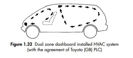
figure 1.32
Dual HVAC
Generally installed at the front of the vehicle under the dashboard and extended to the rear. Dual systems can include up to three zones, driver, front passenger and the rear passengers.All zones have a set of HVAC controls to select the desired level of comfort. This system is common on high specification vehicles and MPVs (Multi Passenger Vehicles) – vehicles with a high capacity.
Booster heater systems
Booster heating systems are generally used for the following reasons:
1. Large interior cabin space.
2. Efficient engine combustion with low heat output, additional heat input required.
3. Large interior space (MPV – Multiple Passenger Vehicle).
4. Vehicles operating in extreme weather conditions.
The benefits of such a system are as follows:
1. Improved visibility due to rapid demist.
2. Shorter cold start period improving catalytic converter efficiency and less engine wear.
3. Improved passenger comfort.
PTC heaters
Booster heaters can be as simple as an additional water pump fitted to accurately control/boost coolant through the heat exchanger fitted inside the vehicle to improve heating capacity, or a separate unit which can provide additional heat input to the coolant or air distribution by burning fuel (fuel heaters) or electricity (PTC – Positive Temperature Coefficient – heaters).
Booster heaters should not be confused with dual heating and air-conditioning systems. Dual systems are extensions of the same system and provide heating and cooling control within designated zones inside a vehicle.
The PTC heater unit has an element mounted on a ceramic base and installed in the heater casing. It directly heats up the air flow entering the passenger compartment.
The key characteristics of a PTC additional heater are:
● rapid heating after starting the vehicle;
● light and compact design;
● the unit cannot overheat;
● maintenance free.


figure 1.33 1.34
The PTC heater element consists of small metallised ceramic plates, which are layered alternately along the unit core (1), see Figures 1.33 and 1.34 with aluminium radiator elements. These layers are held together by spring elements in a frame. The aluminium elements provide the electrical contacts.They also transfer heat to the passing heater air flow. In order to prevent electrical short circuits due to metal foreign bodies, a heat-resistant plastic mesh with an aperture of 0.8 mm is located on the heater element. The heater element is divided into separate heating circuits with a ratio of one third to two thirds so that the heating power can be adapted to suit different requirements. PTC heater elements act as a positive temperature coefficient resistor. This means that its resistance value is relatively small at low temperatures and increases with higher temperatures. A high current flows initially when a voltage is applied to the cold PTC element, as a result of which it heats up. As the temperature rises, so does the resistance. This results in a reduced current draw.The time taken to stabilise the current is approximately 20 seconds.The temperature of the additional heater depends on the rate of heat transfer to the surrounding area. If the rate of heat transfer is good, for example, a cold low humidity condition will have a greater temperature difference and allow for a greater rate of heat transfer, therefore the resistance will remain low. Once the air has warmed and the heat transfer rate reduces the PTC unit will start to increase in temperature due to the inability to give up heat.This will cause the


figure 1.35 1.36
resistance on the unit to increase and thus reduce the current flow. The reduced current flow maintains or reduces the temperature. If the opposite occurs and the heater manages to give up heat to the surrounding air then the unit will cool and the resistance will reduce. This will increase current flow through the unit and increase the unit’s temperature.As a result of these specific resistance characteristics, it is not possible for the PTC element to overheat. The maximum surface temperature is around 165°C.
The unit is only operated at low ambient temperatures ( 15°C, supplied by air temperature sensor) and when insufficient heat can be supplied via the coolant-based heating system ( 73°C, information supplied by coolant temperature sensor) and low alternator (generator) loadings. The PTC heater consumes a great deal of current so it can only be operated when the engine is running and its operation is phased. Phased operation means that the unit is treated like a three bar electric heater. One bar at a time is switched on so the load on the alternator (generator) is progressive and not sudden. The load will also affect the idle speed and emissions.
The heating power is around 1 kW when fully operating.This places additional loading on the vehicle electrical system.Vehicles with PTC additional heaters are fitted with a more powerful generator.

figure 1.37
Diesel fuel booster system
If a vehicle cannot provide adequate heated coolant to a heat exchanger then it may use a fuel booster to provide the additional heat input. There is a number of manufacturers using such a system due to ultra efficient diesel combustion systems and the large interior space that requires heating (e.g. Multi Passenger Vehicles (MPVs); Fig. 1.35 and 1.36). This is often between 1 and 3 kW. At maximum output the fuel penalty is 0.38 litres/hour and the operating temperature is between 40 and 80°C. Once above 80°C the unit shuts down. Such units can provide a variable output often dependent upon the measured temperature of the coolant flowing to the heat exchanger and the exterior air temperature. Such a unit may use air or coolant to transfer heat from the unit to the interior of the vehicle.
All the starting, regulating and run-on functions are controlled fully automatically. The main unit is divided into four main sections – heat exchanger, combustion chamber, fan assembly and control module. Figure 1.37 shows the unit with the coolant inlet (B) and outlet (A) on top of the unit.This feeds the heat exchanger section which allows coolant to flow around the outside of the core. The inside of the core is the combustion chamber which contains a glow plug (3), flame sensor (2) and fuel and air inlet. The combustion is initiated by a glow plug fed with fuel which is quantified by the metering unit (7). The glow plug is switched off after a certain time when the flame has stabilised. The fan assembly/combustion blower (1) provides a fresh supply of air to the combustion chamber. After combustion the heat flows from the inside of the heat exchanger which is then conducted through the exchanger’s walls by the coolant. Because the heating power output depends on coolant temperature, sensors are fitted to the heat exchanger housing monitoring coolant temperature to and from the unit. This information is used to govern the unit’s heat output to the vehicle’s heat exchanger. The output temperature sensor and combustion sensor are used for failsafe purposes in case the unit fails, e.g. overheats. All information is monitored by the ECU (6) which has the ability to communicate
with diagnostic equipment. Because the system is electronically controlled, integration into an existing HVAC (Heating, Ventilation and Air-Conditioning) system can be easily achieved.
The booster heater is switched off due to a malfunction if:
1. no ignition takes place after a second attempt at starting (after 90 seconds);
2. the flame is extinguished during operation and a fresh attempt at starting fails;
3. the overheating sensor responds in the event of overheating (125°C);
4. the voltage is over- or undershot;
5. the glow plug, metering pump or temperature sensors or fresh air blower are faulty.
The booster heater can be tested as soon as the ignition is switched on. A fault code can be
read out during a diagnostic check.
Use of an A/C system as a heat pump
With the use of highly efficient diesel engines, hybrid vehicles, and electric fuel cell technology, water-based cooling systems often do not offer the heating capacity for passenger compartments. The vapour compression cycle A/C system can be used as a heat pump. This process is explained in section 1.5.


0 comments :
Post a Comment