This section is reproduced from the Compressor Service Manual Sanden SD6V12 (courtesy of Sanden International (Europe) Ltd)

To The Reader
Service shall be given at risk of owner, user, operator or service personnel of the A/C system and/or the compressor for which this Service Manual is destined. Sanden International (Europe) Ltd shall neither assume responsibility nor be kept liable for any loss or damage to the human life or body and/or the property which occurs or has occurred in conducting or in relation to services carried out in accordance with or in reference to this Service Manual.
1.0 Prechecks
Unusual noise not due to compressor
Unusual noises may be caused by components other than the compressor.
1. Compressor mounting – check for:
- Loose belt – see belt tension specifications.
- Broken bracket or compressor mounting ear. Replace broken component.
- Missing, broken, or loose mounting bolts. Replace, reinstall, or tighten.
- Flush fit of compressor to bracket and vehicle engine. Replace any part not properly fitted.
- Loose or wobbling crankshaft pulley. Check for damage to pulley, incorrect center bolt torque or center bolt bottoming. Repair to vehicle manufacturer’s specifications.
- Bad idler pulley bearing. Replace if necessary.
2. Other engine components – check for noise in:
- Alternator bearing
- Air pump (if present)
- Water pump bearing
- Valves
- Timing belt or chain
- Power steering pump (if present)
- Loose engine mount bolts.
Unusual noises due to compressor
- Suction pressure less than about 5 psig can cause unusual noise. Charge refrigerant to proper amount and test by applying heat to evaporator to increase suction pressure.
- Clutch bearing – see clutch check.
- Oil level – insufficient oil can cause unusual noise. See oil level check.
- Valve Noise – test for valve plate assembly failure per valve plate check.
System pressure release
Before disconnecting any lines,always make sure that the refrigerant has been removed from the A/C system by recovering it with the appropriate equipment. When working on compressors, always be sure to relieve internal pressure first. Internal compressor pressure can be relieved by removing the oil plug (if necessary) or by removing shipping caps/pads from both ports.
Recovery of refrigerant
Never discharge refrigerant to the atmosphere. Always use approved refrigerant recovery
equipment.
Handling of refrigerant
Always wear eye and hand protection when working on an A/C system or compressor.
Ventilation
Keep refrigerants and oils away from open flames. Refrigerant can produce poisonous gases in
the presence of a flame. Work in a well-ventilated area.
Avoid use of compressed air
Do not introduce compressed air into an A/C system due to the danger of contamination.
2.0 Compressor specifications
SD6V12 assembly torques

SD6V12 PAG oil
The SD6V12 compressors leave the factory production line with SP10 PAG oil. The quantity of oil in the SD6V12 compressors supplied to Opel is 120 cc.When an existing compressor is to be installed on a vehicle it is necessary to add the correct amount of compressor oil. This should be done via the oil plughole.
3.0 Service operations – clutch
3.1 Armature assembly removal
- 1. Insert pins of armature plate spanner into holes of armature assembly.
- 2. Hold armature assembly stationary while removing retaining nut with 14 mm socket wrench (Figure 5.33).

- The armature can be removed by pulling it manually upwards off the splined shaft (Figure 5.34).
Service operations – clutch
Rotor assembly removal
- Remove rotor retaining snap ring using snap ring pliers (Figure 5.35).
- Remove rotor using Sanden removing tool (Figure 5.36).
- The rotor bearing is not changeable as it is staked into position (Figure 5.37).
Service operations – clutch
3.3 Field coil assembly removal
- Remove lead wire clamp screw with Phillips screwdriver so that coil wires are free. Take care not to round off retaining screw head (Figure 5.38).
- Remove coil retaining snap ring using snap ring pliers (Figure 5.39).
- Remove the field coil assembly.
- Remove the shims from the shaft. Use a pointed tool and a small screwdriver to prevent the shims from binding on the shaft (Figure 5.40).


Service operations – clutch
3.4 Field coil assembly installation
- 1. Reverse the steps of section 3. The protrusion on the underside of the coil ring must match hole in the front housing to prevent the movement and rotation of the coil and to correctly locate the lead wire(s).
3.5 Rotor assembly installation
- Place the compressor on support stand, supported at rear end of compressor.
- Set rotor squarely over the front housing boss.
- Place the rotor installer ring into the bearing bore. Ensure that the edge rests only on the inner race of the bearing, not on the seal, pulley, or outer race of the bearing.


- Place the driver into the ring and drive the rotor down onto the front housing with a hammer or arbor press. Drive the rotor against the front housing step. A distinct change of sound can be heard when using a hammer to install the rotor (Figure 5.41).
- Reinstall the rotor retaining snap ring using snap ring pliers (Figure 5.42).

3.6 Armature assembly installation
- Install clutch shims. Note – Clutch air gap is determined by shim thickness. When installing a clutch on a used compressor, try the original shims first. When installing a clutch on a
- compressor that has not had a clutch installed before, first try 1.0, 0.5 and 0.1 mm shims (Figure 5.43). Reinstall the armature on the splined shaft. Manually push the armature down the shaft until it bottoms on the shims.
- Replace retaining nut and torque to specification: 19.6 1.9/0.9 Nm (Figure 5.44).
- Check air gap with feeler gauge. Specification is 0.4–0.8 mm. If air gap is out of specification remove armature and change shims as necessary (Figure 5.45).


4.0 Service operations – shaft seal
4.1 Replacement of lip type shaft seal
Note – Lip seal assembly and felt ring must never be reused. Always replace these
components.
- Be sure all gas pressure inside the compressor has been relieved.
- Remove clutch assembly as detailed in Section 3 Service operation clutch assembly.
- Remove the felt ring assembly using a small screwdriver to pry it out (Figure 5.46).
- Remove seal snap ring with internal snap ring pliers (Figure 5.47).
- Use lip seal removal and installation tool to remove lip seal assembly. Twist the tool until the two lips on the tool engage the slots in the lip seal housing and pull the seal out with a twisting motion (Figure 5.48). Clean out shaft seal cavity completely. Make sure all foreign material is completely removed.


Service operations – shaft seal
- Place shaft seal protector sleeve over compressor shaft. Inspect the sleeve to ensure that it has no scratches and is smooth so that the lip seal will not be damaged. Make sure there is no gap between the end of the sleeve and the seal surface of the shaft (Figure 5.49).
- Engage the lips of the seal removal and installation tool with the slots in the new lip seal housing. Make sure the lip seal assembly, especially the O-ring, is clean. Dip the entire lip seal assembly, on the tool, into clean refrigerant oil. Make sure the seal assembly is completely covered with oil.
- Install the lip seal over shaft and press firmly to seat. Twist the tool in the opposite direction to disengage it from the seal and withdraw the tool (Figure 5.50).
- Reinstall shaft seal snap ring with internal snap ring pliers. Bevelled side should face up (away from the compressor body). Ensure that the snap ring is completely seated in the groove.


- Tap new felt ring assembly into place.
- Reinstall clutch assembly as detailed in Section 3 Service operation clutch assembly.


5.0 Service operations – cylinder head
5.1 Cylinder head, valve plate removal and installation
- Be sure all internal compressor pressure has been relieved.This can be achieved by undoing the oil plug slowly (refer to section 6).
- Remove cylinder head bolts (Figure 5.51).
- Use a small hammer and gasket scraper to separate the cylinder head from the valve plate. Be careful not to scratch the gasket surface of the cylinder head.
- 4. Carefully lift the cylinder head from the valve plate (Figure 5.52).
- It is recommended that both the head gasket (between the cylinder head and the valve plate) and the block gasket (between the valve plate and the cylinder block) be replaced at any time the cylinder head is removed. However, if no service is required to the valve plate, it may be left in place. If the valve plate comes loose from the cylinder block, the block gasket must be replaced.
- Carefully remove old head gasket from top of valve plate with gasket scraper. Be careful not to disturb the valve plate to cylinder block joint if valve plate is to be left in place. If valve plate comes loose from cylinder block, proceed to section 5.2 Valve plate removal.
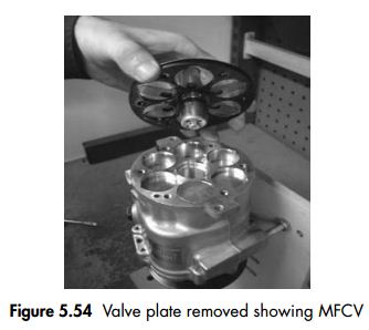
5.2 Valve plate removal
- Using a small hammer and gasket scraper carefully separate valve plate from cylinder block. Be careful not to damage sealing surface of cylinder block (Figure 5.53).
- Inspect reed valves, retainer and MFCV. Replace valve plate assembly if any part is damaged (Figure 5.54).
- Carefully remove any gasket material remaining on valve plate, cylinder block or cylinder head.
5.3 Valve plate and cylinder head installation
- Coat new block gasket with clean refrigerant oil.
- Install block gasket.Align new gasket to location pin holes and orifice(s). Notch (if present) should face same direction as oil plug or adaptor,


- Place valve plate on cylinder block with discharge valve, retainer and nut facing up (away from cylinder block) and location pins properly located in holes.
- Ensure that there is no residual oil in each bolt hole. If oil is present it must be removed to prevent thread damage.
- Coat head gasket with clean refrigerant oil.
- Install head gasket over location pins on the cylinder block, checking for correct orientation.
- Install cylinder head on the locating pins on the cylinder block.
- Install cylinder head bolts and tighten opposite bolts alternately to avoid distortion of cylinder head (Figure 5.55).

6.0 Service operations – replacement of oil plug
6.1 Remove the oil plug using a 17 mm socket or spanner. To replace, coat the sealing O-ring with oil and reinstall using the torque wrench.Tightening torque 14.7 4.9 Nm. Note – the compressor crank chamber is pressurised.The oil plug must never be removed while the compressor is attached to a pressurised system. The correct oil must be used on plug installation. SD6V compressors use Sanden SP-10 PAG oil.


7.0 Service operations – replacement of high pressure relief valve (HPRV)
7.1 Remove the high pressure relief valve using a 16 mm socket or spanner (Figure 5.57).
7.2 To replace coat the sealing O-ring with oil and reinstall using a torque wrench.
7.3 Tightening torque of HPRV 9.8 1.9 Nm.
Note – the correct oil must be used on HPRV installation. SD6V compressors use Sanden
SP-10 PAG oil.
8.0 Service tools
8.1 Special tools for service requirements detailed in this manual.


Note – General rotor puller available from any tool manufacturer
9.0 Compressor replacement
- Replacement with new compressor. New compressors are supplied with sufficient refrigerant oil for the air-conditioning system. If a new compressor is replacing an existing compressor, it is necessary to take some oil out of the new compressor, so that the oil amount in the new compressor is the same as the quantity of oil removed in the old compressor. Note – if a new compressor is installed without the excess oil being drained, the refrigerating capacity of the air-conditioning system will be reduced. Replace the oil plug as quickly as possible after draining oil and keep the A/C system sealed whenever possible to minimise moisture absorption of oil in the compressor.
- Replacement with used or repaired compressor. When a repaired or previously used compressor, which does not contain oil, is to be installed in the vehicle the correct oil should be added via the oil filler plug hole. SD6V compressors use Sanden SP-10 PAG oil. The quantity of oil to be added is the same as the quantity of oil, which was contained, in the removed compressor. Therefore whenever a compressor is removed from a vehicle it is important to drain out the oil and measure its quantity in a measuring cylinder. Shouldinadequate oil be charged to the replacement compressor, seizure is likely due to lubrication failure. Replace the oil plug as quickly as possible after draining oil and keep the A/C system sealed whenever possible to minimise moisture absorption of oil in the compressor.
Oil level measurement (in vehicle)
Oil level in the compressor should be checked when a system component has been replaced,
when an oil leak is suspected, or when it is specified as a diagnostic procedure.
- Run the compressor for 10 minutes with the engine at idle.
- Recover all refrigerant from the system, slowly so as not to lose any oil.
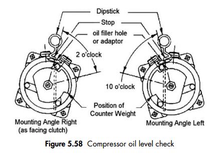
- Determine the mounting angle of the compressor from horizontal (i.e. oil plug or adaptor on top). This is most readily done by using a machinist’s universal level, if access to the compressor permits.
- Remove the oil filler plug. Using a socket wrench on the armature retaining nut, turn the shaft clockwise until the counterweight is positioned as shown.
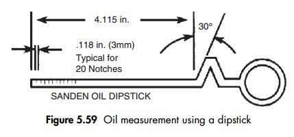
- Insert oil dipstick up to the stop, as shown in Figure 5.58, with the angle pointing in the correct direction.
- Remove dipstick and count number of notches covered by oil.
- Add or subtract oil to meet the specifications shown in the table.
- Reinstall oil plug. Seat and O-ring must be clean and not damaged. Torque to 11–15 ftlb (15–20 Nm, 150–200 kgfcm).

Compressor repaired internally and reinstalled in the system
- Before any internal repair is done, drain the oil from the compressor.
- Remove the oil plug and drain as much oil as possible into a suitable container.
- Remove the caps (if present) from suction and discharge ports.
- Drain oil from the suction and discharge ports into a suitable container while turning the haft clockwise only with a socket wrench on the armature retaining nut.
- Measure and record the amount of oil drained from the compressor.
- Inspect the oil for signs of contamination such as discoloration or foreign material.
- Perform repair to the compressor.
- Add the same amount of new oil to the compressor as was measured in step 2. Be sure to use the correct oil for the compressor.
- Reinstall oil plug. Seal and O-ring must be clean and not damaged. Torque to 11–15 ftlb (15–20 Nm, 150–200 kgfcm). Be careful not to cross thread the oil plug.
- It is recommended that the oil quantity be confirmed after reinstallation of the compressor to the vehicle.


- Drain oil from the old compressor; measure and record the amount as per the procedure.
- Drain oil from the new compressor.
- Add new oil of the correct type to the new compressor. Use the same quantity as was removed from the old compressor in step 1. Figure

5.62 Figure 5.63
- Reinstall oil plug. Seal and O-ring must be clean and not damaged. Torque to 11–15 ftlb (15–20 Nm, 150–200 kgfcm).
- It is recommended that the oil quantity be confirmed after installation of the newcompressor to the vehicle.


Sanden SP-20 refrigerant oil for R134a SD compressors
Sanden provides field service containers of SP-20 PAG oil for Sanden SD-series compressors in convenient 250 cc cans. These cans are designed to withstand moisture ingression. Always keep the cap of the can tightly closed when not handling the oil. Cans are packed in ‘six-packs’ and available through your Sanden representative. Material safety data is also available. Sanden limits the warranty of SD compressors for field service with the condition that only Sanden-approved SP-20 is utilized. ‘Six-pack’ of 250 cc cans of SP-20 oil – Sanden Number 7803–1997.


0 comments :
Post a Comment