Showing posts with label Service and Repair. Show all posts

Tuesday, November 22, 2016

Fixed Orifice Valve Remove and Replace

7:09 AM CN Damian
iklan bawah share

Tools

The following tools (Figs 5.62–5.64) are available for removing and installing the fixed orifice tube:


  1. Remover and installer for fixed orifice tube (with threaded sleeve) 34–004.
  2. Remover for damaged fixed orifice tube (without threaded sleeve) 34–005.


The tool with the number 34–004 is hooked into the housing of the fixed orifice tube.The fixed orifice tube can then be withdrawn from the line by turning the threaded sleeve. This tool is also used to install the fixed orifice tube. This must be slid into the line as far as the shoulder. 

If the housing of the fixed orifice tube breaks off during removal, the damaged fixed orifice tube can be removed with tool 34–005 in conjunction with the threaded sleeve of tool 34–004. For this purpose, the tool is screwed into the fixed orifice tube.
iklan bawah postingan

Replacement and Adjustment of Compressor Components

7:06 AM CN Damian
iklan bawah share
This section is reproduced from the Compressor Service Manual Sanden SD6V12 (courtesy of Sanden International (Europe) Ltd)


To The Reader
Service shall be given at risk of owner, user, operator or service personnel of the A/C system and/or the compressor for which this Service Manual is destined. Sanden International (Europe) Ltd shall neither assume responsibility nor be kept liable for any loss or damage to the human life or body and/or the property which occurs or has occurred in conducting or in relation to services carried out in accordance with or in reference to this Service Manual.

1.0 Prechecks
Unusual noise not due to compressor 
Unusual noises may be caused by components other than the compressor.
1. Compressor mounting – check for: 

  • Loose belt – see belt tension specifications.
  • Broken bracket or compressor mounting ear. Replace broken component.
  • Missing, broken, or loose mounting bolts. Replace, reinstall, or tighten.
  • Flush fit of compressor to bracket and vehicle engine. Replace any part not properly fitted. 
  • Loose or wobbling crankshaft pulley. Check for damage to pulley, incorrect center bolt torque or center bolt bottoming. Repair to vehicle manufacturer’s specifications. 
  • Bad idler pulley bearing. Replace if necessary.

2. Other engine components – check for noise in: 

  • Alternator bearing
  • Air pump (if present)
  • Water pump bearing
  • Valves
  • Timing belt or chain
  • Power steering pump (if present)
  • Loose engine mount bolts.

Unusual noises due to compressor

  1. Suction pressure less than about 5 psig can cause unusual noise. Charge refrigerant to proper amount and test by applying heat to evaporator to increase suction pressure.
  2. Clutch bearing – see clutch check.
  3. Oil level – insufficient oil can cause unusual noise. See oil level check.
  4. Valve Noise – test for valve plate assembly failure per valve plate check.

System pressure release 
Before disconnecting any lines,always make sure that the refrigerant has been removed from the A/C system by recovering it with the appropriate equipment. When working on compressors, always be sure to relieve internal pressure first. Internal compressor pressure can be relieved by removing the oil plug (if necessary) or by removing shipping caps/pads from both ports. 

Recovery of refrigerant
Never discharge refrigerant to the atmosphere. Always use approved refrigerant recovery
equipment. 

Handling of refrigerant
Always wear eye and hand protection when working on an A/C system or compressor.

Ventilation
Keep refrigerants and oils away from open flames. Refrigerant can produce poisonous gases in
the presence of a flame. Work in a well-ventilated area.

Avoid use of compressed air 
Do not introduce compressed air into an A/C system due to the danger of contamination.

2.0 Compressor specifications
SD6V12 assembly torques


SD6V12 PAG oil
The SD6V12 compressors leave the factory production line with SP10 PAG oil. The quantity of oil in the SD6V12 compressors supplied to Opel is 120 cc.When an existing compressor is to be installed on a vehicle it is necessary to add the correct amount of compressor oil. This should be done via the oil plughole.


3.0 Service operations – clutch
3.1 Armature assembly removal 

  1. 1. Insert pins of armature plate spanner into holes of armature assembly.
  2. 2. Hold armature assembly stationary while removing retaining nut with 14 mm socket wrench (Figure 5.33).
  3. The armature can be removed by pulling it manually upwards off the splined shaft (Figure 5.34).


Service operations – clutch

Rotor assembly removal 


  1. Remove rotor retaining snap ring using snap ring pliers (Figure 5.35).
  2. Remove rotor using Sanden removing tool (Figure 5.36).
  3. The rotor bearing is not changeable as it is staked into position (Figure 5.37).

Service operations – clutch

3.3 Field coil assembly removal 

  1. Remove lead wire clamp screw with Phillips screwdriver so that coil wires are free. Take care not to round off retaining screw head (Figure 5.38).
  2. Remove coil retaining snap ring using snap ring pliers (Figure 5.39).
  3. Remove the field coil assembly.
  4. Remove the shims from the shaft. Use a pointed tool and a small screwdriver to prevent the shims from binding on the shaft (Figure 5.40).


Service operations – clutch
3.4 Field coil assembly installation 


  1. 1. Reverse the steps of section 3. The protrusion on the underside of the coil ring must match hole in the front housing to prevent the movement and rotation of the coil and to correctly locate the lead wire(s).

3.5 Rotor assembly installation


  1. Place the compressor on support stand, supported at rear end of compressor.
  2. Set rotor squarely over the front housing boss.
  3. Place the rotor installer ring into the bearing bore. Ensure that the edge rests only on the inner race of the bearing, not on the seal, pulley, or outer race of the bearing.

  4. Place the driver into the ring and drive the rotor down onto the front housing with a hammer or arbor press. Drive the rotor against the front housing step. A distinct change of sound can be heard when using a hammer to install the rotor (Figure 5.41).
  5. Reinstall the rotor retaining snap ring using snap ring pliers (Figure 5.42).

3.6 Armature assembly installation


  1. Install clutch shims. Note – Clutch air gap is determined by shim thickness. When installing a clutch on a used compressor, try the original shims first. When installing a clutch on a
  2. compressor that has not had a clutch installed before, first try 1.0, 0.5 and 0.1 mm shims (Figure 5.43). Reinstall the armature on the splined shaft. Manually push the armature down the shaft until it bottoms on the shims.
  3. Replace retaining nut and torque to specification: 19.6 1.9/0.9 Nm (Figure 5.44).
  4. Check air gap with feeler gauge. Specification is 0.4–0.8 mm. If air gap is out of specification remove armature and change shims as necessary (Figure 5.45).


4.0 Service operations – shaft seal
4.1 Replacement of lip type shaft seal 
Note – Lip seal assembly and felt ring must never be reused. Always replace these
components.

  1. Be sure all gas pressure inside the compressor has been relieved.
  2. Remove clutch assembly as detailed in Section 3 Service operation clutch assembly.
  3. Remove the felt ring assembly using a small screwdriver to pry it out (Figure 5.46).
  4. Remove seal snap ring with internal snap ring pliers (Figure 5.47).
  5. Use lip seal removal and installation tool to remove lip seal assembly. Twist the tool until the two lips on the tool engage the slots in the lip seal housing and pull the seal out with a twisting motion (Figure 5.48). Clean out shaft seal cavity completely. Make sure all foreign material is completely removed.


Service operations – shaft seal


  1. Place shaft seal protector sleeve over compressor shaft. Inspect the sleeve to ensure that it has no scratches and is smooth so that the lip seal will not be damaged. Make sure there is no gap between the end of the sleeve and the seal surface of the shaft (Figure 5.49).
  2. Engage the lips of the seal removal and installation tool with the slots in the new lip seal housing. Make sure the lip seal assembly, especially the O-ring, is clean. Dip the entire lip seal assembly, on the tool, into clean refrigerant oil. Make sure the seal assembly is completely covered with oil.
  3. Install the lip seal over shaft and press firmly to seat. Twist the tool in the opposite direction to disengage it from the seal and withdraw the tool (Figure 5.50). 
  4. Reinstall shaft seal snap ring with internal snap ring pliers. Bevelled side should face up (away from the compressor body). Ensure that the snap ring is completely seated in the groove.


  5. Tap new felt ring assembly into place.
  6. Reinstall clutch assembly as detailed in Section 3 Service operation clutch assembly.
5.0 Service operations – cylinder head

5.1 Cylinder head, valve plate removal and installation 


  1. Be sure all internal compressor pressure has been relieved.This can be achieved by undoing the oil plug slowly (refer to section 6).
  2. Remove cylinder head bolts (Figure 5.51).
  3. Use a small hammer and gasket scraper to separate the cylinder head from the valve plate. Be careful not to scratch the gasket surface of the cylinder head.
  4. 4. Carefully lift the cylinder head from the valve plate (Figure 5.52).
  5. It is recommended that both the head gasket (between the cylinder head and the valve plate) and the block gasket (between the valve plate and the cylinder block) be replaced at any time the cylinder head is removed. However, if no service is required to the valve plate, it may be left in place. If the valve plate comes loose from the cylinder block, the block gasket must be replaced.
  6. Carefully remove old head gasket from top of valve plate with gasket scraper. Be careful not to disturb the valve plate to cylinder block joint if valve plate is to be left in place. If valve plate comes loose from cylinder block, proceed to section 5.2 Valve plate removal.
5.2 Valve plate removal

  1. Using a small hammer and gasket scraper carefully separate valve plate from cylinder block. Be careful not to damage sealing surface of cylinder block (Figure 5.53).
  2. Inspect reed valves, retainer and MFCV. Replace valve plate assembly if any part is damaged (Figure 5.54).
  3. Carefully remove any gasket material remaining on valve plate, cylinder block or cylinder head.
5.3 Valve plate and cylinder head installation

  1. Coat new block gasket with clean refrigerant oil.
  2. Install block gasket.Align new gasket to location pin holes and orifice(s). Notch (if present) should face same direction as oil plug or adaptor,

  3. Place valve plate on cylinder block with discharge valve, retainer and nut facing up (away from cylinder block) and location pins properly located in holes.
  4. Ensure that there is no residual oil in each bolt hole. If oil is present it must be removed to prevent thread damage.
  5. Coat head gasket with clean refrigerant oil.
  6. Install head gasket over location pins on the cylinder block, checking for correct orientation.
  7. Install cylinder head on the locating pins on the cylinder block.
  8. Install cylinder head bolts and tighten opposite bolts alternately to avoid distortion of cylinder head (Figure 5.55).

6.0 Service operations – replacement of oil plug

6.1 Remove the oil plug using a 17 mm socket or spanner. To replace, coat the sealing O-ring with oil and reinstall using the torque wrench.Tightening torque 14.7 4.9 Nm. Note – the compressor crank chamber is pressurised.The oil plug must never be removed while the compressor is attached to a pressurised system. The correct oil must be used on plug installation. SD6V compressors use Sanden SP-10 PAG oil.


7.0 Service operations – replacement of high pressure relief valve (HPRV)

7.1 Remove the high pressure relief valve using a 16 mm socket or spanner (Figure 5.57).
7.2 To replace coat the sealing O-ring with oil and reinstall using a torque wrench.
7.3 Tightening torque of HPRV 9.8 1.9 Nm.

Note – the correct oil must be used on HPRV installation. SD6V compressors use Sanden
SP-10 PAG oil. 


8.0 Service tools

8.1 Special tools for service requirements detailed in this manual.


Note – General rotor puller available from any tool manufacturer


9.0 Compressor replacement


  1. Replacement with new compressor. New compressors are supplied with sufficient refrigerant oil for the air-conditioning system. If a new compressor is replacing an existing compressor, it is necessary to take some oil out of the new compressor, so that the oil amount in the new compressor is the same as the quantity of oil removed in the old compressor. Note – if a new compressor is installed without the excess oil being drained, the refrigerating capacity of the air-conditioning system will be reduced. Replace the oil plug as quickly as possible after draining oil and keep the A/C system sealed whenever possible to minimise moisture absorption of oil in the compressor. 
  2. Replacement with used or repaired compressor. When a repaired or previously used compressor, which does not contain oil, is to be installed in the vehicle the correct oil should be added via the oil filler plug hole. SD6V compressors use Sanden SP-10 PAG oil. The quantity of oil to be added is the same as the quantity of oil, which was contained, in the removed compressor. Therefore whenever a compressor is removed from a vehicle it is important to drain out the oil and measure its quantity in a measuring cylinder. Shouldinadequate oil be charged to the replacement compressor, seizure is likely due to lubrication failure. Replace the oil plug as quickly as possible after draining oil and keep the A/C system sealed whenever possible to minimise moisture absorption of oil in the compressor.

Oil level measurement (in vehicle)
Oil level in the compressor should be checked when a system component has been replaced,
when an oil leak is suspected, or when it is specified as a diagnostic procedure. 

  1. Run the compressor for 10 minutes with the engine at idle.
  2. Recover all refrigerant from the system, slowly so as not to lose any oil.
  3. Determine the mounting angle of the compressor from horizontal (i.e. oil plug or adaptor on top). This is most readily done by using a machinist’s universal level, if access to the compressor permits.
  4. Remove the oil filler plug. Using a socket wrench on the armature retaining nut, turn the shaft clockwise until the counterweight is positioned as shown.
  5. Insert oil dipstick up to the stop, as shown in Figure 5.58, with the angle pointing in the correct direction.
  6. Remove dipstick and count number of notches covered by oil.
  7. Add or subtract oil to meet the specifications shown in the table. 
  8. Reinstall oil plug. Seat and O-ring must be clean and not damaged. Torque to 11–15 ftlb (15–20 Nm, 150–200 kgfcm). 


Compressor repaired internally and reinstalled in the system
  1. Before any internal repair is done, drain the oil from the compressor.
    • Remove the oil plug and drain as much oil as possible into a suitable container.
    • Remove the caps (if present) from suction and discharge ports.
    • Drain oil from the suction and discharge ports into a suitable container while turning the  haft clockwise only with a socket wrench on the armature retaining nut.
  2. Measure and record the amount of oil drained from the compressor.
  3.  Inspect the oil for signs of contamination such as discoloration or foreign material.
  4.  Perform repair to the compressor.
  5. Add the same amount of new oil to the compressor as was measured in step 2. Be sure to use the correct oil for the compressor.
  6. Reinstall oil plug. Seal and O-ring must be clean and not damaged. Torque to 11–15 ftlb (15–20 Nm, 150–200 kgfcm). Be careful not to cross thread the oil plug.
  7. It is recommended that the oil quantity be confirmed after reinstallation of the compressor to the vehicle.


Sanden compressor replaced by a new Sanden compressor of the same type

  1. Drain oil from the old compressor; measure and record the amount as per the procedure.
  2. Drain oil from the new compressor.
  3. Add new oil of the correct type to the new compressor. Use the same quantity as was removed from the old compressor in step 1. Figure

    5.62 Figure 5.63
  4. Reinstall oil plug. Seal and O-ring must be clean and not damaged. Torque to 11–15 ftlb (15–20 Nm, 150–200 kgfcm).
  5. It is recommended that the oil quantity be confirmed after installation of the newcompressor to the vehicle.
Sanden SP-20 refrigerant oil for R134a SD compressors
Sanden provides field service containers of SP-20 PAG oil for Sanden SD-series compressors in convenient 250 cc cans. These cans are designed to withstand moisture ingression. Always keep the cap of the can tightly closed when not handling the oil. Cans are packed in ‘six-packs’ and available through your Sanden representative. Material safety data is also available. Sanden limits the warranty of SD compressors for field service with the condition that only Sanden-approved SP-20 is utilized. ‘Six-pack’ of 250 cc cans of SP-20 oil – Sanden Number 7803–1997.

iklan bawah postingan

Retrofitting

6:59 AM CN Damian
iklan bawah share
Conversion from R12 to R134aIf the R12 vehicle air-conditioning system is optional, run it at idle with the A/C blower on high speed for 5 minutes to maximise the amount of oil in the compressor.
  1. Recover all R12 refrigerant from the vehicle’s A/C system.
  2. Remove the compressor from the vehicle.
  3. Remove the compressor oil plug and then drain as much mineral oil as possible from the compressor body.
  4. Drain mineral oil from the cylinder head suction and discharge ports while turning the shaft with a socket wrench on the clutch armature retaining nut.
  5. Remove the existing R12 receiver-drier or accumulator-drier from the vehicle and discard. Allow as much oil as possible to drain from the A/C hoses.
  6. Change any O-rings on the receiver-drier or accumulator-drier joints to approved HNBR
  7. O-rings; replace any other O-rings that have been disturbed. 8. Replace the receiver-drier or accumulator-drier with a new R134a compatible one containing XH7 or XH9 desiccant.
  8. If a CCOT system is being repaired due to compressor damage, or foreign material is found in the oil drained from the system, this foreign material must be removed from the system. At this time an inline filter should be installed in the liquid line. Allow as much oil as possible to drain from the A/C lines when installing the filter. Change any O-rings disturbed in the installation of the filter to approved HBNR O-rings.
  9. Perform any necessary repairs to the compressor or A/C system.
  10. Using the original refrigerant oil quantity specification, add SP-20 or SP-10 oil to the compressor (SP-10 for TR, SDV-710, SDB-705, SDB-706 and SDB-709; SP-20 for all other SD compressors).
  11. Replace the compressor oil plug O-ring with an HNBR O-ring.
  12. Reinstall the compressor oil plug. The plug seat and O-ring must be clean and free of damage. Torque the plug to 11–15 ft lb (15–20 N m, 150–200 kgf cm).
  13. Change any seals at the compressor ports to approved HNBR seals.
  14. Reinstall the compressor to the A/C system. Evacuate the A/C system for at least 45 minutes to a vacuum of 29 inHg, using R12 equipment, to remove as much R12 as possible from the residual mineral oil.
  15. Remove all R12 service equipment and disable the R12 service fittings to prevent any refrigerant other than R134a from being used. Permanently install R134a quick connect service fittings to the A/C system.
  16. Connect R134a service hoses and other equipment. Re-evacuate the system for 30 minutes using the R134a equipment.
  17. Charge the A/C system with R134a. Generally, about 5% (by weight) less than the R12 charge amount is required. Leak check the system per SAE J1628 procedure.
  18. If the A/C system is a CCOT type, which has been repaired due to damage or the discovery of foreign material in the oil drained from the system, run the system for 60 minutes to capture this material in the filter installed in step 9. Recover the refrigerant, remove anddispose of the filter, reconnect the lines, evacuate for at least 45 minutes, and recharge theA/C system. This step should not be necessary for TXV systems, since the drier is fitted with an internal filter.
  19. Check the A/C system operating parameters. The system should function correctly within acceptable limits of temperatures and pressures. This will ensure that the correct amount of R134a has been charged.
  20. In extreme circumstances when expected cooling performance cannot be achieved and high discharge pressures are experienced, it may be necessary to add more condensingcapacity to the A/C system.An electric fan(s) and/or larger capacity condenser can be used.
  21. Replace all R12 compressor labels with retrofit labels per SAE J1660 in order to provide information on the R134a retrofit which has been performed.

iklan bawah postingan

Odour Removal

6:54 AM CN Damian
iklan bawah share

Musty smell in interior
Occasionally, the air-conditioning system can cause a musty damp smell in the interior of the vehicle. This is due to particles of dirt, which are carried into the evaporator housing with the induced fresh air, sticking to the evaporator fins covered with condensation. When the airconditioning system is switched off, a moist warm environment is created in which the partially organic deposits of micro-organisms and fungi are broken down.This process produces unpleasant smells which are conveyed into the interior of the vehicle when the air-conditioning system is switched on again. The smell rapidly disappears due to the continuous change of air when the system is running. However, it recurs after every break in operation.Vehicles used in moist warm climates are more frequently affected by this type of smell. Often it also occurs in vehicles with horizontal evaporator fins. The droplets of condensation are unable to drain away completely from these fins and a constantly damp environment is produced which promotes the multiplication of micro-organisms and fungi. The interior of the evaporator housing must not be allowed to remain continuously moist if the smell is to be avoided. Therefore, the drainage lines must be cleaned regularly. In addition, it is important to ensure that as little dirt as possible enters the evaporator housing. Vehicles parked regularly under trees pick up particularly large amounts of dirt.

Action to cure smells
If smells ever occur, the interior of the evaporator housing must be treated with a chemical which has a disinfecting and deodorising action (see Figure 5.13). This chemical is distributed


throughout the evaporator housing with the aid of a special spray gun. Before using the chemical, locate the precise cause of the smell. This chemical can only be used to cure smells emanating from the evaporator housing. Other sources of smells such as damp carpets or the like must be treated differently. Before treatment with the chemical, the evaporator must be completely dry. This is achieved by operating the system with maximum heating at the highest blower speed in fresh air mode with the vents opened for about 15 minutes. The compressor must not be allowed to operate (unplug the low pressure switch or the magnetic clutch). Moisture in the air would condense on the cold evaporator again immediately. The blower motor or the blower resistor can be removed to gain access to the evaporator housing, depending on the type of vehicle. If possible, the housing must be cleaned by hand from inside. If a particularly large accumulation of dirt is found, it is imperative to check whether the screens and filters are intact. The chemical is distributed over the entire surface of the evaporator with the spray gun through the opening. The blower motor or resistor can be refitted while the chemical is allowed to work for 10 minutes. To ensure that the chemical cannot be carried away by condensation, it must be allowed to dry on the evaporator. For this, the vehicle heating must be operated for a further 15 minutes without the compressor running. Then the interior of the vehicle must be aired thoroughly. The low pressure switch or the magnetic clutch can be reconnected. On completion of the work, the vehicle interior must be aired for 30 minutes.


iklan bawah postingan

System Flushing

6:52 AM CN Damian
iklan bawah share
Automotive air-conditioning system flushing has become in recent months a very controversial subject. A lack of guidance and commitment from OEMs regarding flushing and the varying opinions from industrial bodies have left the aftermarket with no conclusive flushing method or flushing procedure. Consequently, the end user is left bewildered and/or unprepared to make a decision on the best flushing method available and service to offer his customers. 

Autoclimate, an aftermarket supplier, has considered all OEM methods and procedures, taken into account numerous industry opinions and subsequently developed a liquid refrigerant flushing procedure, which minimises valuable labour time and at minimal cost to the end user.

An automotive air-conditioning system may require flushing for several reasons: 

1. Retrofit (conversion from R12 to R134a).
2. System contamination.
3. System component failure. 


Retrofitting is the name given to a procedure that involves converting an R12 automotive airconditioning system, which uses refrigerant R12, into a system that uses refrigerant R134a. Consequently any R12 system which needs repair must to be retrofitted to R134a, if system longevity is to be considered. System contamination is a phrase that covers a wide scope of potential issues. System contamination is considered when any other substance outside design parameters has been introduced into the A/C system. Debris, burnt lubricant, contaminated lubricant and incorrect lubricant are some of the issues that need to be considered when system contamination has occurred.A low system refrigerant charge will result in poor lubricant circulation, thus increasing friction and heat causing premature system failure. Increased friction and heat will also begin to burn the system lubricant causing it to carbonise inside components, on pipes, seals etc. 

Debris is usually the result of a system component failure, this can vary from fine metal particles to desiccant, a result of a receiver-drier/accumulator failure. Once this debris has begun to circulate in the system, it must be removed. Irreparable damage and expensive repairs are a direct consequence of debris in the A/C system. Debris passing over ‘burnt’ lubricant will begin to adhere to it, and slowly a blockage may form. In these instances the system must be flushed to remove all debris. 

The lubricant must also be flushed from the system and the correct amount and viscosity added; if the flushing procedure and lubricant renewal are not carried out correctly it might result in a repeat failure.The build-up of lubricant/debris can also affect the heat transfer characteristics of both the condenser and the evaporator. Modern condensers and evaporators have multipath parallel circuits, so the possibility of clearing every path that is blocked is unlikely, thus affecting performance. In these instances it may be necessary to remove and replace the component. A similar effect may be experienced if the system has too much lubricant, although flushing will remove excess lubricant. 

Flushing method
The flushing procedure may be carried out in a closed loop configuration (with the system split in two halves) or each individual component separately. Flushing each individual component can be labour intensive and expensive for the customer. Closed loop flushing with liquid refrigerant is a quick, effective method of flushing, which does not introduce any foreign chemicals to the system that may lead to further problems.The flushing process can be improved by 


the introduction of an oil-based cleaning agent. The introduction of oil-based cleaning agents greatly improves the first time removal of oil and debris from the A/C system. By allowing the A/C system to be split into two halves, high side and low side, an effective forward/backward flush can be achieved. Any restrictions in the system, such as the receiver-drier, expansion valve, accumulator or orifice tube, are bypassed. Adaptors have been developed which allow for most restrictions to be bypassed; a set of universal adaptors may also be used for less common vehicles. 


Results

Once the system has been successfully flushed and all contamination/debris removed the system may be reassembled. It is recommended that the receiver-drier/accumulator is always replaced after flushing an A/C system. With the A/C system cleaned, increased heat transfer should result in improved system performance. No contamination, the correct viscosity, and the correct amount of lubricant in the system will ensure that the compressor also operates to system performance expectations. 
iklan bawah postingan

System Oil

6:47 AM CN Damian
iklan bawah share
Lubricant

Refrigeration oil lubricates the moving parts and seals of an A/C system.The oil flows with the refrigerant throughout the system.

Mineral and PAG oil

The type of refrigeration oil used in an A/C system depends on the type of refrigerant. When engineers develop a refrigerant, they simultaneously develop the lubrication oil to use with it. R12 A/C systems use mineral oil as a lubricant. R134a systems use oil made of polyalkylene glycols, commonly called PAG oil. PAG oil and mineral oil are completely incompatible and should never be mixed. Refrigeration oil, is highly refined and free of the additives and detergents found in conventional motor oil. Refrigeration oil flows freely at temperatures well below freezing, and it includes an additive to prevent foaming in the A/C system. Refrigeration oil readily absorbs moisture. If stored improperly, the oil becomes unusable. If you use saturated oil in an A/C system, acids form, damaging seals and other components. Always seal refrigerant oil properly after use, and never reuse oil removed from an operating A/C system.

In an A/C system, the components hold the refrigerant oil.The compressor helps to mix the oil with the refrigerant and circulates it throughout the system. Both oils are available in different viscosities. Always ensure the correct oil type and viscosity is placed into an A/C system. 

Polyol ester oil

Polyol Ester (POE) has good miscibility with HFCs. It is an alcohol-based oil. Its ability to change viscosity with a change in temperature makes it an attractive alternative to PAG oil although some controversy exists which states the POE breaks down into alcohol and acid if in contact with moisture. It is compatible with R12, R134a and CO2-based A/C systems. POE is not an OEM oil and should only be used if specified by the A/C manufacturer. Aftermarket retrofitting is generally associated with the use of POE.


Oil viscosity

The higher the viscosity number the greater the viscosity and the higher its resistance to flow. This means the liquid is thicker.

The following is a list of recommended lubricants for R134a compressor applications:

Behr/Bosch rotary compressors – Ester 10  0   Matsushita (all) – Ester 100
Behr/Bosch piston compressors – PAG 46       Mitsubishi FX80 – PAG 100
Calsonic V5 – PAG 150                                    Mitsubishi FX105 –   PAG 46
Calsonic V6 – PAG 46                                      Nihon (all) – Ester 100
Chrysler RV2 – Ester 100                                 Nippondenso 6P, 10P, 10PA, 10P08E –
                                                                           PAG 46
Chrysler C171, A590 & 6C17 – PAG 46          Nippondenso SP127, SP134 & 6E171 –
                                                                           PAG 46
Diesel/Kiki (Zexel) DKS, DKV &                    Nippondenso TV series – PAG 125
DCW – PAG 46
Ford FS6, FX15, FS10, 10P &                          Panasonic (all) – PAG 46
10PA – PAG 46

When replacing an A/C component, the oil trapped in the component that is being replaced ust also be replaced. Service manuals contain charts describing how much oil to add for various component replacements. Charts that refer to replacing the quantity drain should be gnored.The correct amount of oil must be replaced if the system is to function correctly. If the ystem has a severe oil shortage then replacing the quantity drained will not help the system peration and will not stop the system from eventual failure.This can cause a great deal of customer dissatisfaction and responsibility may be aimed at the last technician who worked onthe system.This is another reason why it is important as a technician to record all work carried ut on a vehicle’s system especially A/C related. Oil removed and oil added must be carefullyrecorded including refrigerant and components.


Oil stains

An oil stain on a connection or joint indicates that refrigerant is leaking from that place. This s because the compressor oil mixed in with the refrigerant escapes with the refrigerant when efrigerant gas leaks out from the refrigeration circuit, causing an oil stain to form at the place here the refrigerant gas is leaking out.

If such an oil stain is found, parts should be retightened or replaced as necessary to stop the as leakage. Gasketed compressor joints and pipe connections are the places where oil stains re most likely to be found, and the condenser, due to its position, is prone to leaks so it is mportant to check all these places. R12 mineral oil leaves a clear oil stain but R134a PAG oil vaporates so this test will not be visual without the aid of a UV lamp.The UV lamp will highlight tracer fluid inside the system. Most manufacturers now place tracer dye inside the system rom manufacture.The amount of oil lost depends on the size of the leak and the length of time t was leaking.After you repair a leak, replace the amount of lost oil. Carefully measure the oil emoved during evacuation and replace it.

Note – overfilling the system with refrigerant oil reduces the cooling effect. Follow the nstructions provided by the manufacturer of the servicing unit when topping up the efrigerant oil. When topping up the refrigerant oil, make sure that the filling equipment hose, container) is clean and dry.The oil container must be sealed immediately after use. 
iklan bawah postingan

Monday, November 21, 2016

Refrigerant Recovery, Recycle and Charging

10:00 AM CN Damian
iklan bawah share
A/C service units
Most A/C machines are separate units combined into a Refrigerant Management System (RMS). An RMS contains a recovery machine, vacuum pump, electronic scales and an LCD control panel. The unit often includes very simple programmes allowing the technician to select automatic recovery, recycle, evacuation and charging procedures. Some units include databases for
vehicle information and flushing capabilities.

The unit’s pipe work, connectors, switches and gauges are generally colour coded:
Red for the High Pressure (HP) side, also referred as ‘liquid side’ of the A/C system.
Blue for the Low Pressure (LP) side, also referred as the ‘vapour side’ of the A/C system.


Other colours are used to assist in service operations directing the technician to carry out certain procedures, e.g. yellow service hose.When the unit is not in use all valves should be closed.

An A/C system can be charged with refrigerant in liquid or vapour form. The charging process is carried out by measuring the refrigerant charge weight. This is the only approved method of charging an A/C system.

The RMS (Refrigerant Management Station) unit is capable of automatic refrigerant recovery,  cycle, evacuation and recharging. The unit also has a database on the oil quantities for different manufactured vehicles, which is updatable. The unit can also flush A/C systems using appropriate adapters.

Some RMS units can be used with multiple refrigerants.

Main components of a service station

Low pressure gauge
This gauge is a compound gauge and measures the low pressure side of the air-conditioning system and is coloured blue. It will also give an indication of the vacuum depression when the system is being evacuated. If the vehicle has a suspected leak that is very slight, this gauge may not be able to detect it.


High pressure gauge
This gauge measures the high pressure side of the air-conditioning system, and is coloured red. When the air-conditioning system operation is being checked, the various modes can be seen to operate on this gauge with the different pressure alterations being indicated as they are switched. The relationship between the pressure readings on the two gauges provides a reliable guide to the functioning of the system and an indication of when problems exist.


Note – on R12 systems the couplings for connection to the service connectors are the same. Therefore, it is imperative to note the colour coding. Incorrect connection would damage components of the servicing unit. In R134a systems different couplings are used. The connectors on the high pressure and low pressure sides are of different diameters.This prevents incorrect connection or different refrigerants being mixed with one another.

Low pressure valve
This should be coloured blue to signify it is part of the low pressure side of the charging station system. It must not be overtightened. It should be turned using the fingertips until an impedance is felt (signifying it is closed) and then gently pinched to lock it.When the valve is reopened the operator should be able to ‘crack’ the locking torque without using undue pressure (with the fingertips).


High pressure valve
This should be coloured red to signify it is part of the high pressure side of the charging station. This valve must be tightened and unlocked using the same method as the other valves.

High pressure pipe
Colour coded red, it is usually of a suitable length so that a clearance can be maintained between the charging station and the vehicle. Minimising the possibility of the charging station damaging the vehicle paint work.The end connection to the vehicle system has a Schrader type valve depressor built into it.


Note – at no time should the pipe be uncoupled at the charging station while it is connected to the vehicle.


There is a hose gasket fitted to provide a good seal between the vehicle system and the charging trolley.This should be inspected for wear or damage at frequent intervals.The sealing properties of this gasket can be prolonged with the application of a small amount of refrigerant oil before use.

Low pressure pipe
Coloured blue to signify that it is part of the low pressure circuit. It is usually the same length as the high pressure pipe with the same type of end connector fitted.

The hose gasket fitted into the connector requires the same attention and maintenance as for the high pressure pipe gaskets.


Manifold assembly
This unit allows the charging station to evacuate, recharge and test the vehicle air-conditioning system in situ without disconnecting any hoses. For discharge purposes the pipe connecting the manifold to the charging station must be disconnected so that the refrigerant 12 can be discharged into a recovery station.This enables the operator to measure the amount of refrigerant oil lost from the air-conditioning system during the discharge operation.


To avoid the possibility of refrigerant entering the vacuum pump during the system discharging operation, ensure the vacuum pump valve is closed.The manifold is designed so that when the high and low pressure pipes are connected to the vehicle air-conditioning system, with both of the valves in the ‘off’ position, the gauges will read the vehicle system pressure. When the manifold is set to this position, the charging station is isolated from the air-conditioning system. The valves can then be opened, connecting the charging station to the air-conditioning system as required.

Vacuum pump valve
The vacuum pump valve’s function is to switch the vacuum pump depression to the manifold, and to isolate the vacuum pump when refrigerant is being circulated through the charging system.

Refrigerant control valve to the charging cylinder
This valve, which is normally coloured red, connects the refrigerant bottle (fitted on the rear of the charging station) to the charging cylinder. It can be finely controlled so that refrigerant can be slowly measured into the charging cylinder.

Refrigerant control valve to the manifold assembly
This red coloured valve must be treated with the same consideration as the other valves. Its function is to control the refrigerant flow to the vehicle, via the manifold. If refrigerant is allowed to flow too quickly it will boil and vaporise, reducing the vacuum depression, which is required to draw the refrigerant into the vehicle system.


Charging cylinder gauge
The gauge is connected to the top of the charging cylinder sight glass. Its function is to measure the pressure variations of the refrigerant in the charging cylinder that can then be calibrated to a reading on the plastic shroud that surrounds the cylinder. This can be done by taking a reading from the charging cylinder pressure gauge and comparing it to the table that is marked around the top of the plastic shroud. Line this reading up with the charging cylinder to indicate the pressure of the refrigerant in the measuring cylinder. There are different types of refrigerant, with the plastic shroud depicting different tables for each of the most common types.


Charging cylinder
This charging cylinder can store and deliver a specific amount of refrigerant to the vehicle airconditioning system with an accuracy of plus or minus 7 grams (4 oz). Dial-a-charge charging cylinders allow the operator to compensate for refrigerant volume fluctuations resulting from temperature variations.This allows the purchase of more economical drums of refrigerant. It also provides a greater degree of accuracy when charging the air-conditioning system, eliminating over- and undercharging, which can lead to problems when the vehicle has gone back into service. 

These cylinders are provided with heating elements that allow the operator to overcome equalisation of pressure between the air-conditioning system and the charging cylinder, which reduces the time required to recharge the system. Simply ‘dial’ the calibrated plastic shroud so that the pressure reading at the top of the shroud corresponds to the gauge reading. The calibrated column that is in line with the sight glass will then show the amount of refrigerant that is in the sight glass at that pressure. The charging cylinder is now ready for the transfer of an accurately measured amount of refrigerant 12 to the vehicle air-conditioning system.


Vacuum pump
This is a very robust pump that enables the vehicle air-conditioning system to be evacuated quickly and effectively.

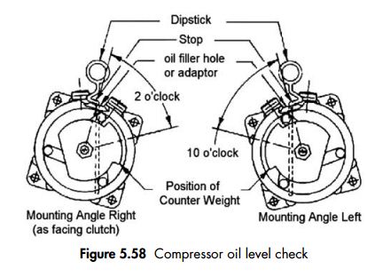
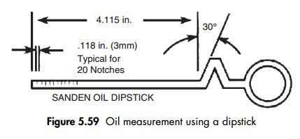
It requires very little routine maintenance, having its own oil circulation system that requires periodic checking according to the manufacturer’s instructions.

Vacuum pump to manifold connecting pipe
This pipe connects the vacuum pump to the vacuum pump valve on the manifold. It requires a good seal so that there are no leaks between the vacuum pump and the manifold.The connections should be periodically checked for tightness.


System evacuation
A vacuum pump may be purchased and used as a separate item. The centre or yellow service hose connects to the vacuum pump and the two hoses on the manifold gauge connect to the low pressure (LP) and high pressure (HP) sides of the system. The vacuum pump should only be attached when system gauge pressure is zero or showing a vacuum. Before using the vacuum pump check the oil via the pump sight glass is satisfactory. Start the pump and open the LP and HP service connectors to apply a vacuum.The reading on the LP gauge should steadily go into vacuum. If the vacuum pump fails to draw a vacuum then the system may have a leak. Periodically check the gauge reading and if unsatisfactory carry out a leak test. If satisfactory progress is made then evacuate for 30 minutes to a pressure of 1.006 bar. Upon satisfactory evacuation of the system shut the manifold gauge valve to the pump and check that the pressure is maintained for 10 minutes minimum, overnight if required. A slight pressure increase may be experienced if trapped refrigerant in the oil boils off. 

System vapour charging
Vapour charging is carried out on the low side (blue hose) of the A/C system where during normal A/C operation vapour is flowing into the compressor.When vapour charging the compressor is running to draw vapour in. The refrigerant cylinder must be positioned so only vapour can leave which is generally the upright position with the blue valve open (vapour valve).A small amount of air is bled (purged) off from the service hoses at the manifold gauge end to ensure that air present in the hoses is removed. Some automated machines do not require air purging.The refrigerant cylinder is placed on electronic scales and weighed at the start and throughout the process of charging the system to monitor that the correct quantity of refrigerant is delivered. The A/C system is initially evacuated to achieve a deep vacuum; the refrigerant vapour will fill the system producing an initial charge level.This produces enough pressure to shut the low pressure switch/sensor, which allows the A/C compressor to engage and the A/C system to operate and draw the rest of the vapour into the system.

System liquid charging
Liquid charging is a much more dangerous process and is carried out on the high pressure (HP) side of the A/C. The HP connector is generally positioned as follows: on the compressor (early models), on the condenser, between the condenser and receiver-drier (TXV) or between the condenser and FOV. Systems that have the HP valve fitted to the compressors should not be liquid charged. This is because there is a danger of the compressor being internally damaged. The engine is not running during liquid charging. A liquid charging process uses high pressure to charge the A/C system which is obtained using either a charging unit or a charging cylinder.

System charging using a charging cylinder
The refrigerant is transferred from its cylinder to a charging cylinder. A charging cylinder as previously discussed has a calibrated shroud used for temperature compensation which is rotated until the graduated number for that refrigerant volume at that pressure is next to the sight column.The refrigerant is transferred to the charging unit by warming the source refrigerant bottle (max. 45°C) and by applying a vacuum to the charging cylinder. The heated source bottle is connected to the charging cylinder. The red ‘liquid’ valve on the source bottle is opened and then air is carefully purged out of the hoses. The valve on the charging cylinder is opened and liquid refrigerant can flow into the unit. Once the correct level is obtained the valve is closed. When the charging cylinder is filled to the required level plug the unit into a 240 V supply and heat the cylinder to about 35°C which is noted on the thermometer. The system can now be filled via the high pressure connection/liquid line. The refrigerant will flow from the red liquid valve on the charging cylinder straight into the A/C system on the high pressure side (normally into the condenser).

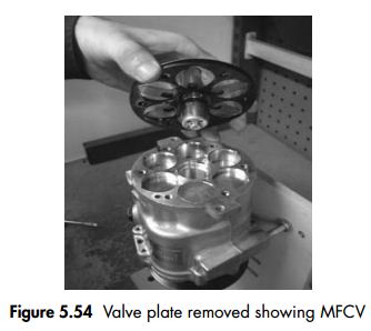
Note – never liquid charge into the compressor because of damage to the valve plate.


Section 1 Service preparation and precautions
When handling refrigerant or carrying out repairs to an automotive air-conditioning system it is recommended that eye protection and gloves are worn. Extreme caution must be taken not to allow any refrigerant to come into contact with the skin and especially the eyes. Liquid refrigerant (R134a) evaporates at approximately 26.3°C, and because it evaporates quickly, it freezes anything it comes into contact with. Care must also be taken to avoid breathing refrigerant or system lubricant vapour. Exposure may irritate eyes, nose and throat. 


Use only approved automotive air-conditioning service equipment. Avoid carrying out airconditioning service repair work in any small unventilated area to avoid asphyxiation. We strongly recommend that all servicing technicians refer to their appropriate COSHH file for more detailed information. Ensure that protective covers are applied to the vehicle before commencing any work. The battery must be disconnected to prevent accidental starting of the engine and the possibility of personal injury if access to service connectors are close to fans, belts etc. Make sure that tools, measuring equipment and parts to be fitted are clean and dry. 

Keep all necessary equipment and tools within easy reach so that the system is not left open any longer than is absolutely necessary. Before undoing any refrigerant lines, joints or connectors, clean off any dirt, moisture, oil etc. in order to prevent contamination of the system.All open connections should be capped or plugged (air tight) immediately to stop dirt, air or moisture getting into the system. Air inside the circuit will damage the system and reduce the cooling effect as it contains moisture.Any O-rings disturbed by undoing unions must always be renewed after lubricating with refrigerant oil prior to fitment. When removing O-rings from couplings, care must be taken not to scratch the sealing face. It is recommended that the receiver-drier/accumulator is replaced if the system has been open to the atmosphere for more than 4 hours (depending on the manufacturer), is physically damaged or has been in service for more than 2 years. Do not remove plugs from new components until each component is ready to be installed into the A/C system, this will limit the amount of air and moisture entering the system. When adding refrigerant oil, ensure that any filling equipment (hose, container etc.) is clean and dry.The oil container must be sealed immediately after use. To ensure the system works correctly after servicing, the system must be evacuated (vacuumed) for a minimum of 30 minutes before recharging.This will remove (by dehydration) any moisture from the system. One of the most important requirements when filling the air-conditioning system is to use clean refrigerant. Any foreign matter including air, moisture, dirt etc. in the air-conditioning circuit will have an adverse effect on refrigerant pressures and impair the system performance. After every repair or service procedure, the system must be leak checked to identify any leaks that may be present.If any leaks are found,the refrigerant within the system must immediately be recovered and the leak repaired.


Section 2 Initial system test
Step 1
Position car in workshop bay.
Switch off engine.
Open bonnet.
Remove charge port caps.

Note – it is recommended that a refrigerant identifier is used to ascertain system refrigerant
type, percentage of air and whether the refrigerant is contaminated prior to commencing.

Refrigerant identifier
A refrigerant vapour sample flows via the low side of the A/C system to an infrared sensor capable of sensing a range of refrigerants and blends. Audible and visual alarms indicate the presence of hydrocarbon-based refrigerants. The percentage of purity as a level of contamination is provided on an LCD screen.A printer port allows the connection to a printer to provide the customer with a detailed report.

Note – if the refrigerant is unknown, established not to be R12 or R134a, then the customer should be informed and advised of appropriate action. The refrigerant should be recovered into a waste bottle and the system oil and receiver/accumulator must be replaced. A system flush could also be carried out before recharging. When sampling a blend a reading will appear showing the different refrigerants and percentages e.g. the percentage of R12, percentage of R134a and % of hydrocarbons. OEMs in the UK do not recommend the use of blends but the US have a range of blends on the market. If blends are used then a fingerprint (percentage of each refrigerant) should be sampled before charging the system so the correct blend percentage of each refrigerant is known.

With the introduction of new CO2 refrigerants the analysers will eventually be updated or superseded.

Refrigerant labels
A simple method of identifying a refrigerant is to look for the A/C system manufacturer’s original label or retrofit label. These are often lost due to the vehicle engine bays being stream cleaned or body repair work being carried out. Service ports often provide evidence of whether the system is R12 or R134a but this cannot be treated as conclusive.


A comparator
A comparator and thermometer with a set of pressure gauges can be used to identify a refrigerant.The comparator or slide rule uses the pressure and temperature relationship of the refrigerant in a saturated liquid/vapour window. This method is not always accurate due to some refrigerants’ performance characteristics being closely related.

With the use of a refrigerant identifier record the refrigerant type and percentage of air in the system. Use a printer if available to connect to the analyser providing the customer with a detailed report.

Reminder
If the refrigerant NCG is 98% or greater then recover and recycle. If below then reclaim using a separate A/C machine (avoid contamination of A/C machine).

Step 2
Once the refrigerant has been identified the correct service equipment should be used.

Note – technicians must ensure that there is sufficient space for the refrigerant in the recovery or waste bottle. A simple calculation must be made. The amount of refrigerant in the system must be added to the space available inside the bottle without exceeding 80% capacity.

Disconnect the refrigerant analyser from the low side of the A/C system. Make sure the low and high side connectors are shut off. Connect the low pressure and high pressure hoses to the A/C system’s low pressure and high pressure service ports.Open hose connectors to allow refrigerant to flow to the RMS (Refrigerant Management System) (Fig. 5.10).

Record system pressures (A/C Off)
Note – if system pressure is at 0 bar go to Section 4 Evacuation.

Step 3
Using a digital thermometer take the ambient temperature reading (Fig. 5.11) near the front of the vehicle and record for reference during system performance tests.


iklan bawah postingan